 Banner Title Products
Introduction of Inelastic Static Analysis in midas Gen
1. Analysis Type for Seismic Design in Gen
Gen provides the following four methods for seismic design.
| Equivalent Seismic Load | Modal Response Spectrum Analysis | Pushover Analysis | Inelastic Time History Analysis |
 |
 |
 |
 |
|
• Static • Elastic |
• Dynamic • Elastic |
• Static • Inelastic |
• Dynamic • Inelastic |
2. Methods of Seismic Response Evaluation by Inelastic Analysis
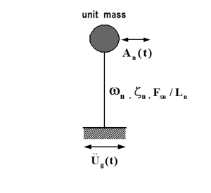
∗ Inelastic Time History Analysis
- Use the seismic response of an equivalent single degree of freedom (ESDOF) system
Using the displacement and resistance force of the converted equivalent single degree of freedom system.
- Use the seismic response of a multi degree of freedom (MDOF) system
Using the representative response of the structure.
∗ Inelastic Static Analysis or Pushover
- Response calculation and performance evaluation based on the capacity design method
Estimate the resistance capacity of a structure through inelastic static analysis.
The required level for seismic load is evaluated by an inelastic response spectrum.
Determine the required strength of the structure by comparing the resistance capacity and the required performance.
- Analysis method: Displacement coefficient method, Capability spectrum method, Direct displacement design method, etc.
3. Traditional Approach for Seismic Design
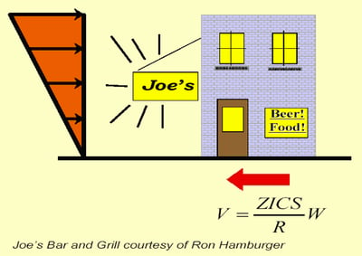
- LinearAnalysis Model
- Simplified Design Base Shear
- Prescriptive Details
- Uncertain Outcomes
- Owners informed of code conformance, but not building performance.
In the event of an actual earthquake, it is impossible to predict the damage patterns of buildings.
→ Prediction of building performance and failure members through inelastic analysis.
4. What is Performance-Based Seismic Design(PBSD)?
It is a seismic design philosophy of a next-generation concept that encompasses all analysis and design procedures necessary for a structure to secure predictable seismic performance and achieve specified performance objective.
→ PBSD is a design method that satisfies performance objective in the event of an earthquake.
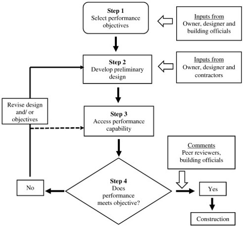
<Procedure of PBSD>
5. What is Capacity Design?
Capacity Design is a design process in which it is decided which objects within a structural system will be permitted to yield (ductile components) and which objects will remain elastic (brittle components).
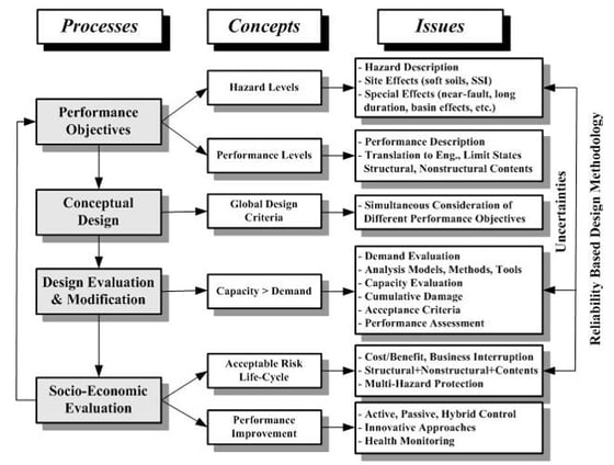
6. Global Framework for Performance-Based Seismic Design (PEER, 2001)
By quantitatively evaluating the damage to structures according to the magnitude of the earthquake load, reliability of safety is secured, and damage to structures and costs incurred during repair and reinforcement are minimized.
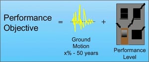
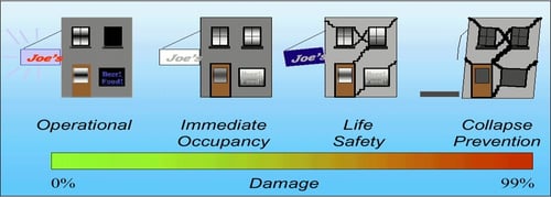
7. What is a Performance Objective?
| Performance Level | Damage Description | Downtime/Loss |
| Immediate Occupancy | Negligible structural damage; essential systems operational; minor overall damage | 24 hours |
| Life Safety | Probable structural and nonstructural damage; no collapse; minimal falling hazards; adequate emergency egress | Possible total loss |
| Collapse Prevention | Severe structural and nonstructural damage; incipient collapse; probable falling hazards; possible restricted access | Probable total loss |
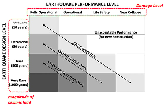
- Safety Critical Performance Level: for facilities with large quantities of hazardous materials (such as toxins, radioactive materials, explosives), that have significant damage potential to the construction and significant external effects.
- Essential Performance Level: for facilities with critical post-earthquake function (such as hospitals, communication centers, police, fire stations, etc.) and facilities containing hazardous materials with limited impact outside of immediate vicinity (refinery, etc.).
- Basic Performance Level: for all other structures.
→ Determine the damage level of the building according to the magnitude of the earthquake and the use of the building.
8. Performance Objective
 Design Codes & Reports
- ATC-40(1996)
- FEMA-273(1997)
- ATC-44(1998)
- SEAOC Blue Book
(7th Edition 1999)
- FEMA-356(2000)
- ATC-55(2002)
It is necessary to set the building performance according to the magnitude of the earthquake (regeneration period).
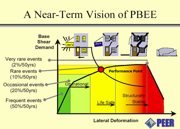
9. Pushover and Performance
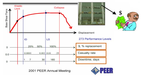
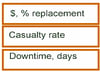 It is possible to evaluate the value of a building accurately, including insurance costs, through accurate seismic performance evaluation
Methods for Inelastic Static Analysis
1. What is Pushover?
Pushover analysis is a static procedure that uses a simplified nonlinear technique to estimate seismic structural deformations. Structures redesign themselves during earthquakes. As individual components of a structure yield or fail, the dynamic forces on the building are shifted to other components. A pushover analysis simulates this phenomenon by applying loads until the weak link in the structure is found and then revising the model to incorporate the changes in the structure caused by the weak link. A second iteration indicates how the loads are redistributed. The structure is “pushed” again until the second weak link is discovered. This process continues until a yield pattern for the whole structure under seismic loading is identified.
Pushover analysis is commonly used to evaluate the seismic capacity of existing structures and appears in several recent guidelines for retrofit seismic design. It can also be useful for performance-based design of new buildings that rely on ductility or redundancies to resist earthquake forces.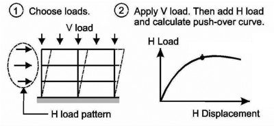
2. Methods for Seismic Performance Evaluation by Pushover Analysis
- Displacement Coefficient Method (DCM): FEMA-273(1997)
Evaluate the inelastic maximum displacement using displacement of elastic system.
Because it is very simple and practical, it is applied in the preliminary design stage.
- Capacity Spectrum Method (CSM): ATC-40(1996)
It is very effective to compare the lateral resistance capacity and the required performance of a structure.
Most widely applied for seismic performance evaluation of existing buildings.
Various methods had researched to improve problems of CSM such as the corrected capability spectrum method and the direct capability spectrum method.
- Modal Pushover Analysis (MPA): Chopra and Goel(2001)
It is an analysis method that secures accuracy while maintaining simple concept and convenient computation.
Reflect characteristics of each mode and consider the higher-order modes effectively.
- Direct Displacement Based Design (DDBD): SEAOC “Blue Book”(1999)
It is the method complemented in the design part of the capability spectrum method (it is a design method based on displacement).
Use of limit displacement considering inelastic failure mechanism.
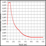
3. Displacement Coefficient Method (DCM) : FEMA-273(1997)
.png?width=500&name=DCM%20(Displacement%20Coefficient%20Method).png)
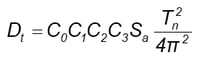
• Target Displacement
Dt = Max. displacement of Elastic system * Dynamic coefficient
• Characteristic of DCM
It is very simple and practical, so it is used in the preliminary design stage.
Dynamic coefficient is a statistical empirical value based on the SDOF response.
Initial stiffness is very important and the effect of strength is ignored.
Elasticity and Inelastic Displacement Ratio by Relation.
• Problems
For periods greater than T0, C1 is overestimated, and for periods less than T0, C1 is underestimated.
Lack of reliability for hysteresis coefficient (C2) and P-Delta consideration coefficient (C3).
Avoid use on soft ground.
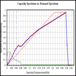
4. Capacity Spectrum Method (CSM) : ATC-40(1996)
* Please find the series 03 for the procedure of CSM
.png?width=500&name=Capacity%20Spectrum%20Method%20(CSM).png)
• Characteristic of DCM
Use equivalent linearization technique.
Reduction of stiffness by secant stiffness.
Consider hysteresis energy dissipation by viscous damping.
Effective expression of stiffness and strength effects at maximum displacement.
• Problems
Applicable only when behavior is determined by a specific domination mode.
Not suitable for weak-story buildings or buildings affected by higher-order modes → Results are unreliable.
5. Modal Pushover Analysis (MPA): Chopra and Goel(2001)
Step 1 : Calculate uncoupled modal equation
Elastic response spectrum procedure
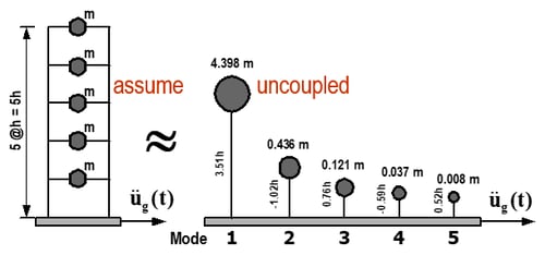 • Base on the Elastic Frequencies and Modes
• Modal Force Distribution :
 Step 2 : Calculate the target displacement for each model
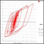
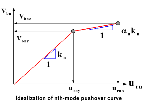
Base Shear vs. Roof Displacement
 • DCM in FEMA-273 :
 → urno
• Yield Displacement and Strain Hardening Ratio
Step 3 : Covert to Inelastic SDOF system
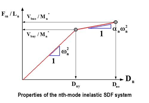 • Spectral Displacement

• Spectral Acceleration
 Step 4 : Dynamic analysis of inelastic SDOF system
 • Inelastic Period
 • Modal Peak Displacement (Dno )
Step 5 : Convert to Modal performance point of MDOF system
 Step 6 : Get the response of MDOF system at performance point
Step 7 : Combination of modal responses (SRSS)


Direct Displacement Based Design (DDBD) : SEAOC “Blue Book”(1999)
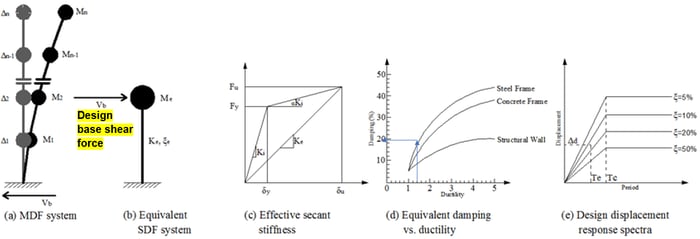 Step 1 : Select a target displacement
Step 2 : Convert to equivalent SDF system (Determine effective mass(me), design displacement (δu)
Step 3 : Calculate effective stiffness(Ke), trial effective period (Te, trial)
Step 4 : Calculate the damping with ductility(= δu / δy)
Step 5 : Calculate effective period (Te) If not Te=Te, trial, go Step 01 If Te=Te, trial, Vb=Ke*δu
Introduction of Capacity Spectrum Method (CSM)
The Capacity Spectrum Method (CSM) is used to evaluate existing structures.
The procedure of CSM compares the capacity of the structure with the demand on the structure.
The capacity is represented by the load-deflection curve and the demand is represented by response spectra.
The intersection of these curves provides an estimate of the response of the structure.
Non-linear behavior of the building is represented using linear response spectra computed for increased damping ratios (β).