 Banner Title Products
OVERVIEW
The main objective is to learn about the process for Determining Wind Loads. There are 3 main definitions here to calculate the wind load.
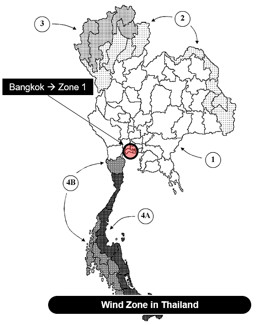
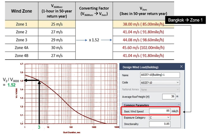
BASIC WIND SPEED, V : Three-second gust speed at 33ft (10m) above the ground in Exposure C (see Section 26.7.3) as determined in accordance with Section 26.5.1.
BUILDING, ENCLOSED : A building that has the total area of openings in each wall, that receives positive external pressure, less than or equal to 4 sq ft (0.37m2) or 1% of the area of that wall, whichever is smaller.
BUILDING, LOW-RISE
Enclosed or partially enclosed building that complies with the following conditions:
1. Mean roof height h less than or equal to 60 ft (18 m).
2. Mean roof height h does not exceed least horizontal dimension.
Table of Contents
2. Outline of Process for Determining Wind Loads
2.1. Determine Basic Wind speed, V, see Section 26.5
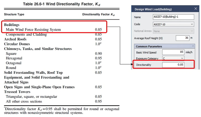
2.2. Determine Wind directionality factor, Kd, see Section 26.6
2.3. Determine Exposure, see Section 26.7
2.4. Determine Topographic factor, Kzt, see Section 26.8
2.5. Determine Ground elevation factor, Ke, see Section 26.9
2.6. Determine Velocity pressure Exposure Coefficients, Kh and Kz, see Table 26. 10-1
2.7. Determine Velocity pressure, see Section 26. 10
2.8. Determine Gust-effect factor, see Section 26. 11
2.9. Determine External pressure coefficient, Cp, see Figs. 27. 3-1
2.10. Determine Design wind pressures, p, see Section 27. 3. 1
2.11. Determine Effective area for each story, Ai
2.12. Calculate Design wind force, V
1. Permitted Design Methods
See ASCE 7-16 26.1.2.1
Method 1. Directional Procedure for buildings of all heights
> Specified in Chapter 27 for buildings meeting the requirements specified therein.
Method 2. Envelope Procedure for low-rise buildings
> Specified in Chapter 28 for buildings meeting the requirements specified therein.
Method 3. Directional Procedure for Building Appurtenances and Other
Structures
> Building Appurtenances : Rooftop structures and rooftop equipment
> Other Structures : Solid freestanding walls and solid freestanding
> Specified in Chapter 29.
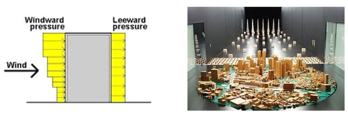
Method 4. Wind Tunnel Procedure for all buildings and all other structures
> Specified in Chapter 31.
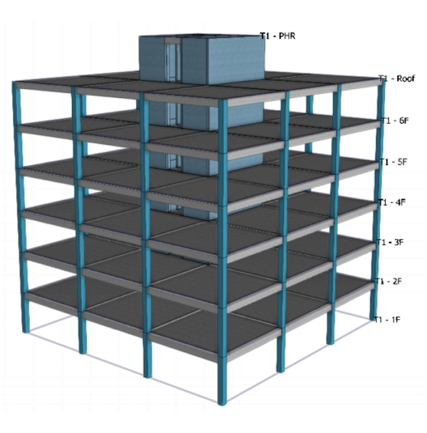
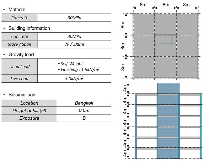
Example Model
2. Outline of Process for Determining Wind Loads
See ASCE 7-16 FIGURE 26. 1-1
There are total 12 steps in this section.
1. Determine Basic Wind speed, V, see Section 26.5
2. Determine Wind directionality factor, Kd, see Section 26.6
 ∗Note
∗Note
The wind directionality factor, Kd, is a nondimensional quantity smaller than unity that reflects the fact that the climatologically and aerodynamically or dynamically most unfavorable wind directions typically do not coincide.
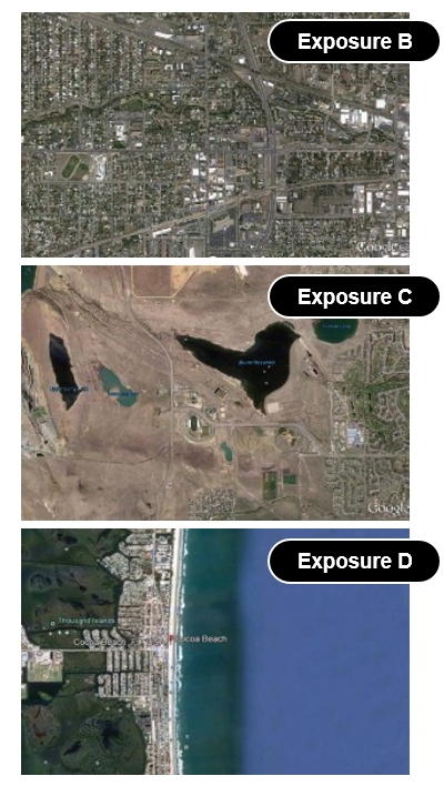
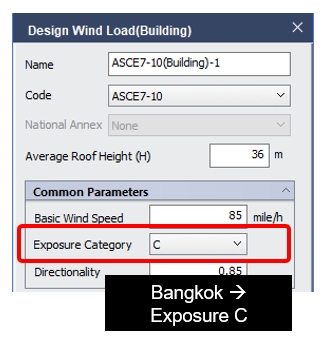
3. Determine Exposure, see Section 26.7
* 4 classification of Exposure
Exposure A (recently deleted in ASCE 7-02) :
Extremely sheltered. Large city centers with tall buildings.
Exposure B :
Urban and suburban areas, wooded areas with many closely spaced obstructions.
Exposure C :
Open terrain with scatter obstructions. Airports, areas that are generally flat open country.
Exposure D :
Flat, unobstructed areas and water surfaces outside hurricane-prone regions. This category includes smooth mud flats, salt flats, and unbroken ice that extend 5,000 ft or 20times the building height in the upwind direction.
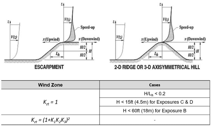
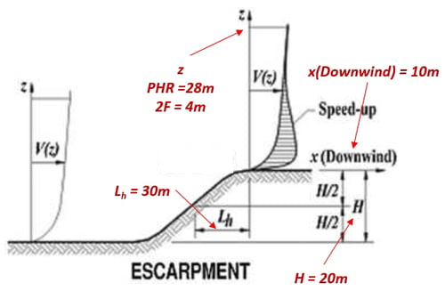
4. Determine Topographic factor, Kzt, see Section 26.8
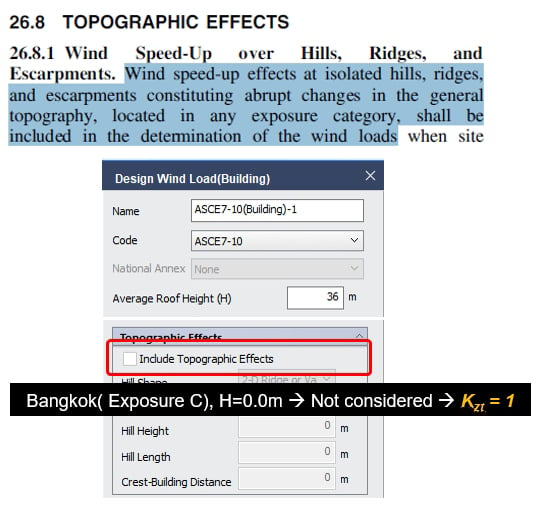
 Here is an example model : When Exposure C, H=20m, and Escarpment.
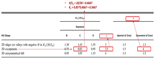
Kzt = (1+K1K2K3)2
= (1 + 0.5667 ∗ (1−|10| / (4∗30)) ∗𝑒−2.5∗28/30 )2 = 1.103 at PHR of example
= (1 + 0.5667 ∗ (1−|10| / (4∗30)) ∗𝑒−2.5∗4/30 )2 = 1.883 at 2F of example
𝐾1=𝐷𝑒𝑡𝑒𝑟𝑚𝑖𝑛𝑒𝑑 𝑓𝑟𝑜𝑚 𝑡𝑎𝑏𝑙𝑒 𝑏𝑒𝑙𝑜𝑤
𝐾2=(1−|𝑥| ∕ (𝜇𝐿_ℎ ) )
𝐾3=𝑒−𝛾𝑧/𝐿ℎ
5. Determine Ground elevation factor, Ke, see Section 26.9
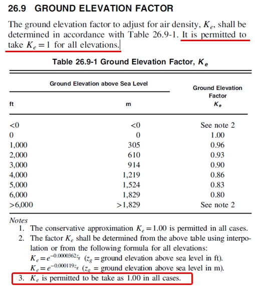
 ∗Note
∗Note
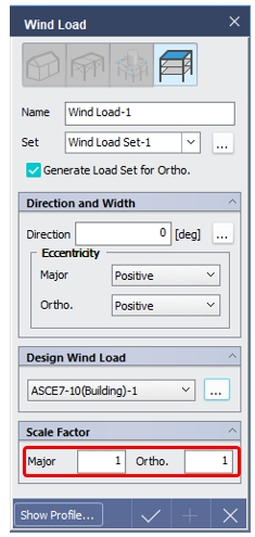
Ke is not considered by nGen.
If you want to reflect Ke, you can control it with the value of “Scale Factor” in Wind Load dialog box.
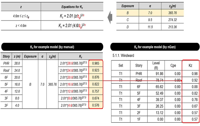
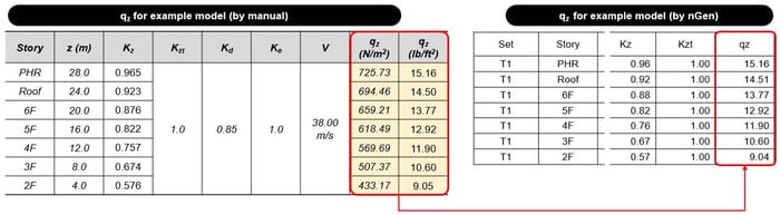
6. Determine Velocity pressure Exposure Coefficients, Kh and Kz, see Table 26. 10-1
7. Determine Velocity pressure, see Section 26. 10
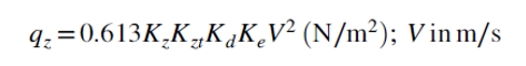 Where,
Kz = velocity pressure exposure coefficient, see Section 26. 10. 1.
Kzt = topographic factor, see Section 26. 8. 2.
Kd = wind directionality factor, see Section 26.6.
Ke = ground elevation factor, see Section 26.9.
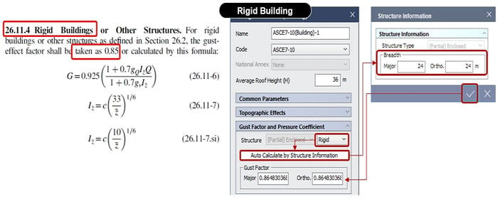
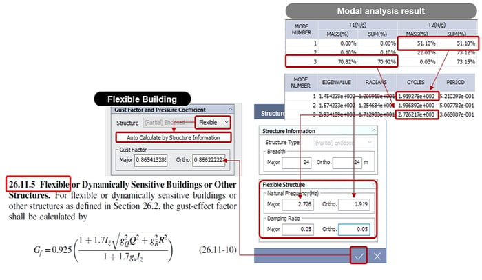
8. Determine Gust-effect factor, see Section 26. 11
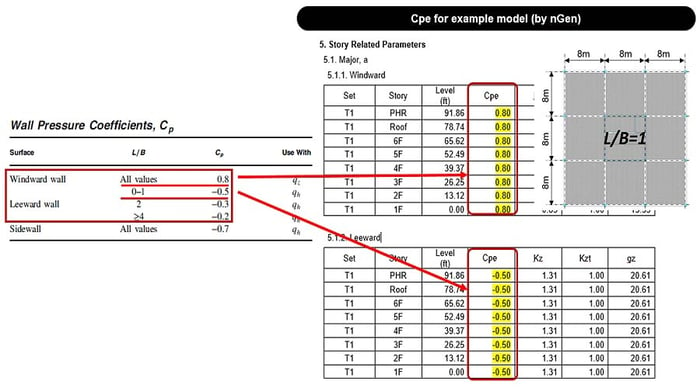
9. Determine External pressure coefficient, Cp, see Figs. 27. 3-1
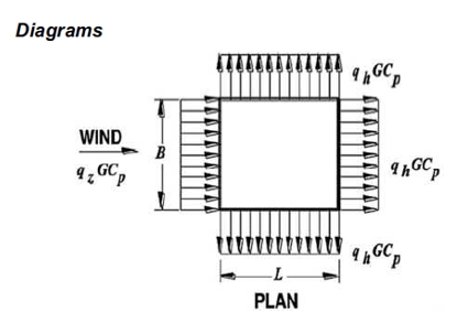
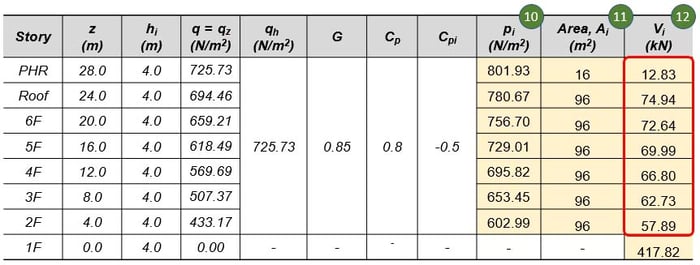
10. Determine Design wind pressures, p, see Section 27. 3. 1
𝑝𝑖= 𝑞𝐺𝐶𝑝 − 𝑞ℎ (𝐺𝐶𝑝𝑖)
11. Determine Effective area for each story, Ai
𝐴𝑖= 0.5(ℎ𝑖+ℎ𝑖−1)𝐵 𝑜𝑟 0.5(ℎ𝑖+ℎ𝑖−1)𝐿
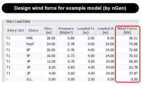
12. Calculate Design wind force, V
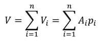
You can download a full version of the white paper for "Fundamentals of Wind Load " at the end of this page.😊