 Banner Title Products
OVERVIEW
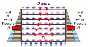
In midas Gen 2018 v1.2, the design of the slab and walls was supported as meshed plate type. Since only out-of-plane moments and shear forces are supported in the case of the slab, the design result could be inaccurate when the slab resists the in-plane axial force and moment, such as the side of the underground slab exposed to earth pressure. Besides, only in-plane axial forces, moments, and shear forces are considered in the case of walls as well. When resisting out-of-plane moments and shear forces caused by earth pressure, such as underground outer walls, the design results are inaccurate.
Plate elements that have not been designed due to the limitations of the meshed plate type so far can be designed in Shell Design, which is supported from Gen 2018 v2.1 or later. Shell Design supports design considering all load factors. Therefore, you can successfully proceed with the project by designing 2D elements under any shape or load condition, such as irregular structures or structures for special purposes by midas Gen.

Project Application
Design Scope
midas Gen provides an automatic design of concrete meshed shell elements. The program also supports section checking when relevant data is specified. With respect to Eurocode, the major capabilities of the program can be summarized as below:
- Auto generation of load combinations as per Eurocode 1990:2002.
The following should be taken care of by the user:
- 2-way shear (Punching) check is not provided in shell design.
|
|
Ultimate Limit State |
|||||
|
|
Flexure |
1-way Shear |
2-Way Shear |
Axial |
||
|
Out-Of-Plane |
In-Plane |
Out-Of-Plane |
In-Plane |
|||
|
Meshed Slab |
√ |
|
√ |
|
√ |
|
|
Meshed Wall |
|
√ |
|
√ |
|
√ |
|
Meshed Shell |
√ | √ | √ | √ |
|
√ |
|
Serviceability Limit State |
|||
|
|
Stress |
Deflection |
Crack Control |
|
Meshed Slab |
√ | √ | √ |
|
Meshed Wall |
|
|
|
|
Meshed Shell |
|
|
|
Table 1. Capabilities of midas Gen with Respect to Eurocode
General
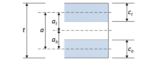
1. Nomenclature
|
a |
Distance between the middle surfaces of the top and bottom layers |
|
ab, at |
Distances between the middle surfaces of bottom and top layers to the middle surface of the shell, respectively |
|
cb, ct |
Depth of bottom and top layers, respectively |
|
cb0 |
First approximation of cb |
|
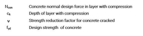
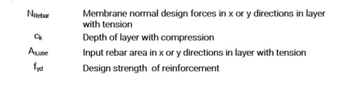
ck |
Depth of layer with compression |
|
ckilim |
Limit depth of layer with compression in order to yield the reinforcement in i direction (x or y) placed in the opposite layer with tension |
|
d |
Depth of the reinforcement |
|
de |
Distance between the upper fiber in the cross-section (i.e. the most compressed one) and the level of the tension reinforcement placed in layer j opposite to k |
|
fck |
Characteristic compressive cylinder strength of concrete at 28 days |
|
fcd |
Design strength of concrete |
|
fyk |
Characteristic yield strength of reinforcement |
|
fyd |
Design strength of reinforcement |
|
Es |
Design value of modulus of elasticity of reinforcing steel |
|
ek |
Distance between the middle layer of the shell element to the centroid of the reinforcement placed in layer k |
|
T |
Depth of the shell element |
|
zya |
Lever arm of Nyat + Nyab related to the center of gravity of the gross section |
|
zyat |
Lever arm of Nyat related to the center of gravity of the gross section |
|
zyab |
Lever arm of Nyab related to the center of gravity of the gross section |
|
zxa, zxat, zxab |
Idem for NEdxat + NEdxab, NEdxat and NEdxab |
|
MEda |
Design value of the applied internal bending moment considered for the first estimation of cb |
|
MEdx, MEdy |
Design value of the applied internal bending moment in x and y directions applied to the shell element |
|
MEdxy |
Twisting design moment applied to the shell element |
|
NEd |
Design value of the applied axial force |
|
NEdx, NEdy |
Normal design forces in x and y directions applied to the shell element |
|
NEdxy |
Shear design force applied to the shell element |
|
NRebar,x, NRebar,y |
Membrane normal design forces in x and y directions in layer with tension |
|
Ncon |
Concrete normal design force in layer with compression |
|
ak |
Angle between crack and x direction, in layer with compression |
|
ecu |
Concrete ultimate compressive strain |
|
ej-i |
Steel strain in i direction, placed in layer with tension, when the depth of compression block in layer with compression is ck |
|
ej-ilim-ak |
Strain measured, in the direction of the crack of layer k(ak), at the level of centroid of reinforcement placed in layer j corresponding to the yield of the steel in i direction |
|
ey |
Tension yield strain of the reinforcement |
|
k |
Stress block factor of the rectangular stress distribution in concrete according Eurocode 2 |
|
r |
Stress |
|
ak |
Angle between the crack in layer with compression and x-direction |
|
vklim |
Depth of the balance point |
Common
|
dB, dT |
Thickness of concrete cover (B : bottom, T : top) |
|
σ1 |
Max. stress of principal stress |
|
σ2 |
Min. stress of principal stress |
|
fcm |
Mean value of concrete cylinder compressive strength |
|
Asi,req |
Required rebar area of i-direction |
|
Asi,use |
Used rebar area of i-direction |
|
ftdi |
Tensile resistance(stress) of rebar of i-direction |
|
f'tdi |
Tensile design stress of rebar of i-direction |
|
σcn |
Concrete compressive resistance strength |
|
σcd |
Concrete design compressive stress |
|
θ |
Shear crack angle |
Subscript
|
a |
Steel |
|
b |
Bottom layer |
|
i |
x or y direction |
|
j |
Layer j, opposite layer to layer k |
|
k |
Layer k (top or bottom layer) |
|
x |
Direction x |
|
lim |
Balance conditions |
|
y |
Direction y |
2. Materials
Concrete
EN1992-1-1:2004 provides specifications for the strength and deformation characteristics of concrete. midas Gen supports a material database as per the specifications. Any of the materials can be easily chosen for analysis as well as design. The following are the strength classes of concrete as identified by the code:
- C12/15
- C16/20
- C20/25
- C30/37
- C35/45
- C40/50
- C45/55
- C50/60
- C55/67
- C60/75
- C70/85
- C80/95
- C90/105
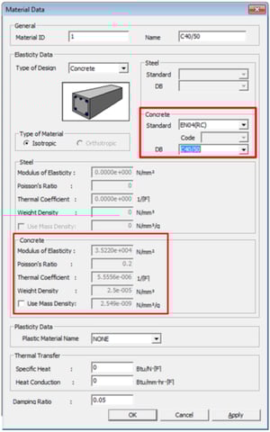
Material name C40/50 implies that the cylinder characteristic strength (fck) at 28 days is 40 MPa and cube characteristic strength (fck,cube) at 28 days is 50 MPa.
The material can be chosen in Material Data dialog Box as shown below. In dialog box, choose Type of Design as “Concrete”. Standard as “EN04(RC)”. Then from DB drop down list any of the above materials can be chosen.
Modulus of Elasticity (Ec)
For materials selected from EN 1992-1-1:2004, the modulus of elasticity is obtained by using the formula as specified by the code (EN1992-1-1:2004):
* Note for Italian users
For Italian user, the program supports the UNI material database. The database includes the following materials:
- Rck 10
- Rck 15
- Rck 20
- Rck 25
- Rck 30
- Rck 35
- Rck 40
- Rck 45
- Rck 50.
For these materials, the user needs to choose the Standard as “UNI(RC)” and then select the desired material.
Poisson’s Ratio
The default value of Poisson’s ratio is used as 0.2. For a different value of Poisson’s ratio user defined material needs to be specified as per Section. User Defined Materials of this guide.
Weight Density
The weight density is used as 25 kN/m3 for all the material from the database. For a different weight density user defined material needs to be specified as per Section. User Defined Materials of this guide.
User Defined Materials
User defined Concrete Material can be specified. Type of Design should be used as Concrete, otherwise, the design cannot be performed for the specified material. Then select the Standard as None to input the user defined material properties. The type of design should not be selected as User Defined.
* Model > Properties > Material
Reinforcement
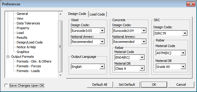
The reinforcement material can be specified in Modify Concrete Materials dialog box as shown in Figure 7. If the material is not specified there, then the default material will be taken as specified in Design/Load Code Environment in Tools > Preferences. Then under the concrete heading user can specify the database for Rebar. The available rebar materials as per Eurocode are as follow:
|
Rebar Material |
Yield Strength (fy) (MPa) |
|
Class A |
400 |
|
Class B |
500 |
|
Class C |
600 |
Table 2. Available Rebar Materials as per EN 1992-1-1:2004
* Note for Italian users
For Italian users, the program supports the UNI database consisting of the following materials:
- FeB22k
- FeB32k
- Feb38k
- Feb44k
To select the above materials, we need to specify the Material Code as “UNI(RC)”.
* Tools > Preferences
Modulus of Elasticity (Es)
For all the reinforcing materials, modulus of elasticity is used as 200 GPa. Different value of the Modulus of Elasticity cannot be specified for reinforcing materials.
** EN1992-1-1:2004 3.1.6(1)
3. Design Strength of Materials
Design Compressive Strength of Concrete (fcd)
The code specifies the following equation for the calculation of the design compressive strength:
Where,
fck: If standard material is used, the value is taken automatically as specified in the code. For a user defined material, we need to specify the fck in Modify Concrete Materials dialog box shown below.
αcc: Coefficient to account for:
- Long term effects on the compressive strength
- Unfavorable effects resulting from the way the load is applied.
It can be specified in the Partial Safety Factor for Materials dialog box as shown in Figure 9.
γc: The partial safety factor for concrete. It depends on the design situation. It can be specified in the Partial Safety Factor for Materials dialog box as shown in Figure 9.
** EN1992-1-1:2004 3.1.6(2)
Design Yield Strength of Reinforcement (fyd)
The yield strength specified for reinforcing material will be used to calculate the design yield strength as per the following specification of code:
Where,
fyk: The characteristic yield strength of reinforcement.
γs: The partial safety factor for steel. It depends on the design situation. It can be specified in the Partial Safety Factor for Materials dialog box as shown in Figure 9.
* Design > Concrete Design Parameter > Modify Concrete Materials
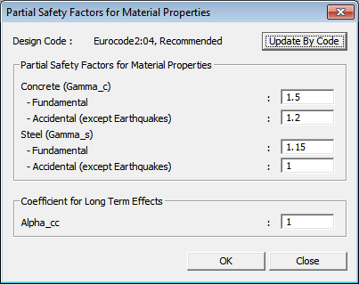 Figure 7. Modify Concrete Material Dialog Box
In the above dialog box, the concrete and rebar material properties can be specified for design.
If standard material is used, the value is taken as specified in the code. In that case, this step is not a mandatory step. If material is user defined, then select 'None' in the Code field and enter the name of material to be used in the Name field. Then, each data field is activated and the strength of materials can be entered.
- Lightweight Concrete Factor (Lambda): This is irrelevant for design as per Eurocode.
- Grade of Main Rebar: The material specified here will be used for the longitudinal reinforcement.
- Grade of Sub Rebar: The material specified here will be used for the stirrups.
* Design > Concrete Design Parameter > Modify Concrete Materials> …
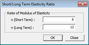
Short/Long Term Elasticity Ratio
For serviceability check as per Eurocode 2, the ratios of the modulus of elasticity of reinforcement to the modulus of elasticity of concrete for short-term and long term can be entered.
The default value for short-term ratio is Es/Ec and 2(Es/Ec) for long-term ratio.
The ratio can be edited in the Modify Concrete Materials Dialog Box. The button next to the Name field, provides access to the Short/Long Term Elasticity Ratio dialog box.
Partial Safety Factors for Materials
* Design > Concrete Design Parameter > Partial Safety Factors for Material Properties
|
Design Situations |
yc |
ys |
|
Persistent & Transient |
1.5 |
1.15 |
|
Accidental |
1.2 |
1.0 |
Table 3. Recommended Values of Partial Safety Factors of Materials
As per EN1990:2002, design situations are classified as:
- Fundamental Design Situations:
- Persistent Design Situations
Relevant during design working life of structure
- Transient Design Situation
Relevant for a shorter duration. eg: execution or repair
- Seismic Design Situation
Relevant during the earthquake
- Accidental Design Situation
Exceptional conditions like fire events, explosions, blast etc.
Specification 5.2.4(2) of EN1998-1:2004 “If more specific data are not available, the values of the partial factors γc and γs adopted for the persistent and transient design situations should be applied”. midas Gen uses the same values of γc and γs for all three design situations i.e, Persistent, Transient & Seismic Design Situations.
The design situation is identified automatically by the program as per the following table:
|
Design Situations |
Description |
|
Fundamental and Seismic |
Load combinations not covered in “Accidental Situation”. |
|
Accidental |
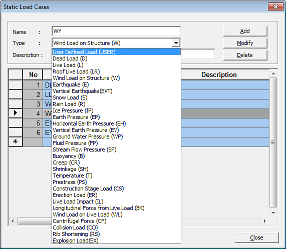
Load Combination including any of the following type of load case, will be classified in Accidental Situation: Live Load Impact (IL) Collision Load (CO) |
Table 4. Classification of Design Situation
Load Case type is specified in the dialog box below:
* Load > Static Load Cases
After identifying the design situation respective partial safety factors for materials are used by the program in design.
4. Input Shell Elements Data
Step 01. Define (sub)domain
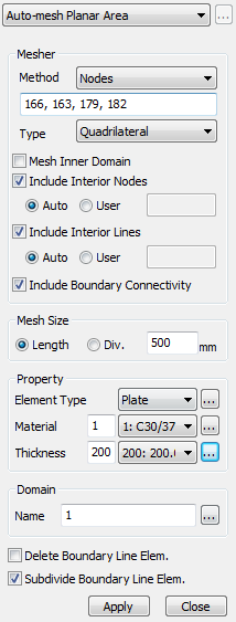
The model must be modeled as a meshed plate for shell design, and a member type must be defined as a shell. With 'Auto-mesh planar area,' one can easily create meshed plate elements.
* Node/Element > Mesh > Auto-mesh
Step 02. Input rebar
In the shell design, there are two functions: Shell Flexural Design, which presents the amount of rebar to satisfy the resistance ratio <1, and Shell Flexural Checking, which evaluates the resistance ratio for the input amount of the rebar. For Shell Flexural Design, a reinforcement standard is required to calculate the reinforcement arrangement information for the calculated reinforcement amount.
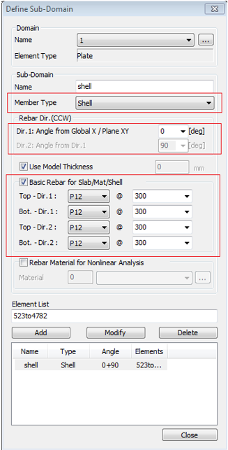
* Node/Element > Mesh > Define Sub-Domain
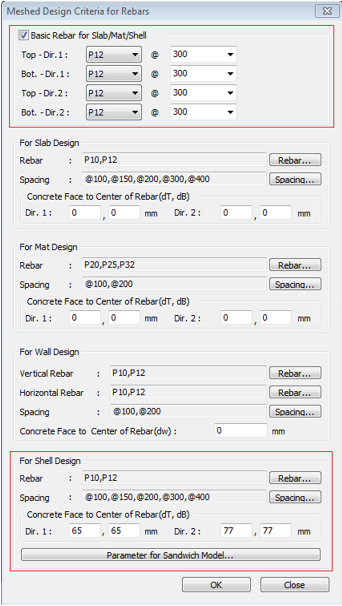
* Design > Design > Meshed Design > Meshed Design Criteria for Rebars
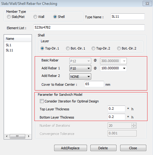
On the other hand, for Shell Flexural Checking, you need to input the rebar arrangement, and you can enter it in the dialog box below. For details on the two dialog boxes above, please refer to the tutorial.
* Design > Design > meshed Design > Slab/Wall/Shell Rebar for Checking
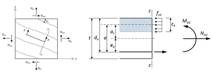
Step 03. Define sandwich thickness and optimal design
Shell Design uses the sandwich model. Sandwich model consists of an outer layer that resists bending moment and axial force, and an inner layer that resists shear force as shown in the figure below.
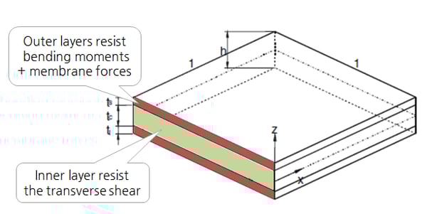 Figure 15. Sandwich Model
In Gen's sandwich model, the thickness of the outer layer is applied as a default value of 20% of the total thickness as shown in Fig.15 above, and the user can directly input the thickness ratio. In addition, it provides a function to calculate the thickness of the outer layer for Optimal Design, which is described in detail in Chapter 3.
Flexural Design
1. Introduction of Shell Design
Design as per Sandwich Panel Theory
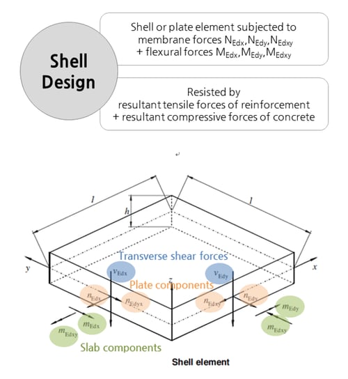
One of the first practical approaches to this problem is the report by Brondum-Nielsen.
This work deals with the shell element as if it were a sandwich element composed of three layers, with the outer layers being responsible for withstanding the membrane force decomposition of the external bending, torsion, in-plane axial and in-plane shear loading.
In addition, to mathematically optimize the amount of rebar, the theory of Tomás and Martí was introduced, and an optimal design function was added.
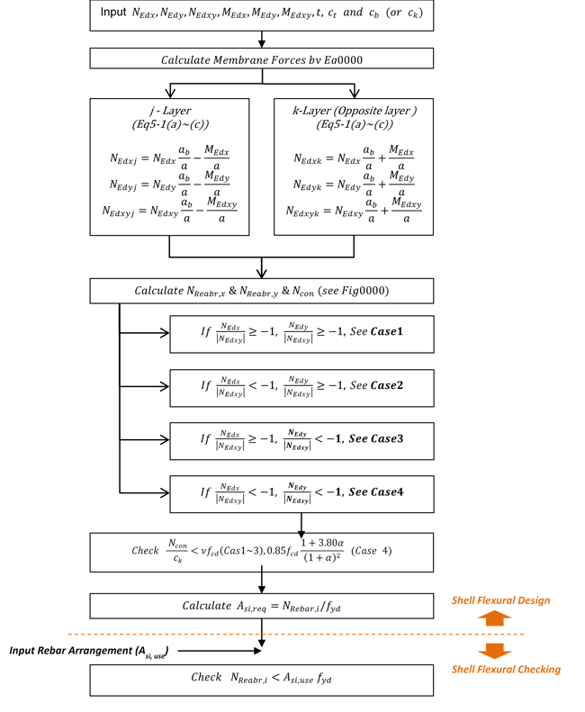
Shell Design Procedure
The procedure for cell design is as follows. Design is carried out by distinguishing whether cracked and non-cracked sections occur due to design member forces.
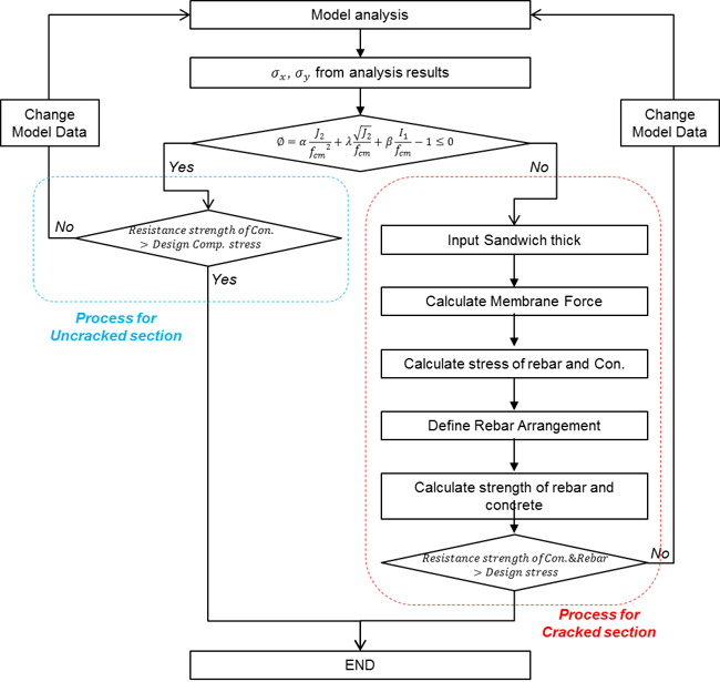 Figure 17. Flow-Chart for Shell Design
Crack Check
The crack judgment of concrete is as shown in Equation 3.1. If ∅ is greater than 0, it is regarded as a cracked section, and if ∅ is less than 0, it is considered an uncracked section.
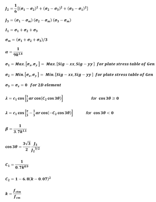
Equation 3.1
∅ = ∝[(J2)/(ƒcm)2] + λ[(√J2)/(ƒcm)] + β[(I1)/(ƒcm)] - 1
∅ ≤ 0 is uncracked section and ∅ > 0 is crackd section.
Where,
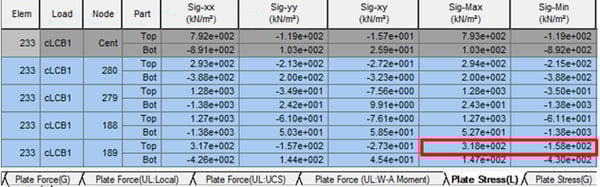
The stress (σ1, σ2) of the shell member in Gen can be checked in the following table. In the table, Sig-Max is σ1 and Sig-Min is σ2.
* Results > Results > Stresses > plane-stress / Plate stress > Plate stress (L) tab
2. Design of Shell with Uncracked Section
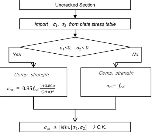
Requirement
In the case of a non-cracked cross-section of ∅≤0 in Equation 3.1, to secure the member's safety, the design principal stress must have a value less than the compressive strength, as shown below.
Equation 3.2
σ2 ≤ σcd max
Compressive Strength Calculation
In the case of a non-cracked cross-section, the compressive strength against the design principal stress is to ensure the member's safety.
Equation 3.3 (a)
If σ1 ≥ 0 and σ2 ≥ 0, Concrete Strength
σcd max = 0.85ƒcd [(1+3.80α)/(1+α)2]
Equation 3.3 (b)
If σ1 ≤ 0 or σ2 ≤ 0, Concrete Strength
σcd max = ƒcd
3. Design of Shell with Cracked Section
Requirement
In the case of a cracked section of ∅≤0 in Equation 3.1, the concrete in the compression section and the reinforcing bar strength in the tension section must be less than the design stress value to secure the member's safety. In midas Gen, a display and report of the results are shown for the stress.
First of all, the following conditions must be satisfied for the safety of concrete in extreme conditions.
Equation 3.4
σcd = Ncon/ck ≤ σcn
Equation 3.5
If σmax < 0, and σmin < 0, in the Case 4. σcn = 0.85ƒcd [(1+3.80α)/(1+α)2]
If σmin > 0, and σmin < 0, in the Case 1~3. vƒcd
Where,
|
Clause |
Recommended |
ITA=UNI-EN1992-1-1 |
|
6.2.2(6) |
ν = 0.6(1-fck/250) (fck in MPa) |
For up to C70/85 ν = 0.5 For C80/95 and C90/105 ν = 0.7(1-fck/250) (fck in MPa) |
Table 6. Strength Reduction Factor for Concrete Cracked, v (when fywd > 0.8fywk)
And the safety of rebar is as follows.
Equation 3.6
ƒ't = (NRebar)/Ck ≤ ƒt = (As,use/Ck)ƒyd
Where,
Flexural Design
Step 1. Membrane forces decomposition of externally applied loads.
In a cracked section, a sandwich model is applied, and the outer layer resists bending and axial force. The axial force acting on the outer layer is given in Equation 3.7 below.
Equation 3.7 (a)
NEdxj = NEdx(ab/a - MEdx/a)
Equation 3.7 (b)
NEdyj = NEdy(ab/a - MEdy/a)
Equation 3.7 (c)
NEdxyj = NEdxy(ab/a - MEdxy/a)
Equation 3.7 (d)
NEdxk = NEdx(ab/a - MEdx/a)
Equation 3.7 (e)
NEdyk = NEdy(ab/a - MEdy/a)
Equation 3.7 (f)
NEdxyk = NEdxy(ab/a - MEdxy/a)
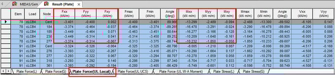
The value of NEdx, NEdy, NEdxy, MEdx, MEdy, MEdxy can be checked in plate force table as shown below.
* Results > Results Tables > Plane Stress > Force (Local)
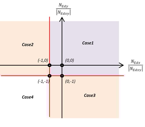
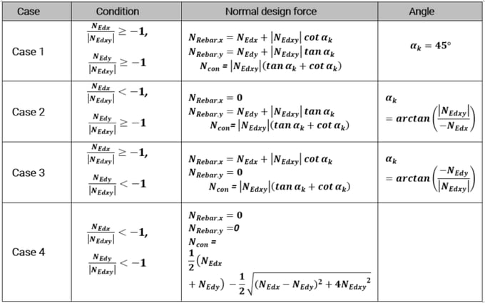
Step 2. Calculate normal design force (NReabr,x , NReabr,y, and Ncon).
The normal design force calculation formula for design review should be applied separately in 4 cases, as shown in Figure 22. According to the ratio of NEdx and NEdy to NEdxy, it is classified into Cases 1 to 4. The tensile and compressive normal design forces for each case are according to Table 8.
Step 3. Calculate required rebar.
In case 1~3, rebar is reinforced in the layer where the tensile force is applied to resist the tensile force.
The required amount of rebar (Asi,req) and reinforcement ratio (ρsi,req) is determined according to Equations 3.8 to 3.9 using the normal design force (NRebar,i) calculated in Step 2.
The amount of rebar and the reinforcement ratio are calculated per unit.
Equation 3.8
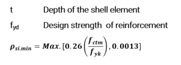
ρsi,req = (NRebar,i/t)/ƒyd≥ ρsi,min
Equation 3.9
Asi,req = NRebar,i * ƒyd = ρsi,reqt
Where,
Step 4. Check concrete strength ratio.
For the normal design force (Ncon) calculated in Step 2, the strength review is performed according to Equations 3.3 to 3.4.
Step 5. Shell flexural strength check when shell members had a rebar data (Asi,use).
If the shell has reinforcement information using user input, etc., the resistance ratio (Rbari) of the shell can be calculated according to Equations 3.10 to 3.11.
Equation 3.10
ƒtdi = Asi,use ƒyd
Equation 3.11
Rbari = (NRebar,i/t)/ƒtdi
Optimal Design
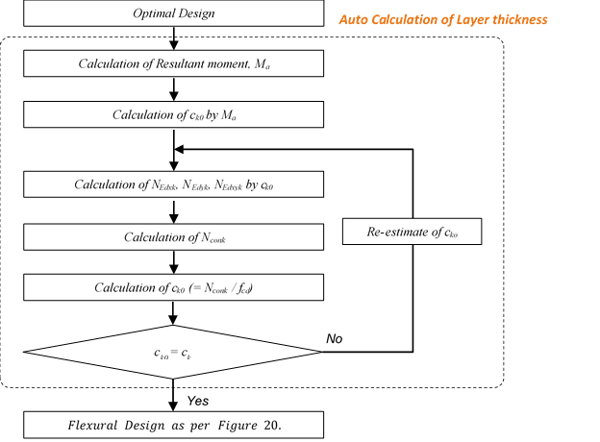
In general, designing the shell proceeds with the assumption that the thickness of the sandwich panel (top layer & Bott. Layer) is 0.2h~0.3h. However, if it is assumed that it is thicker than the membrane force, the distance (a) between the layer centers is shortened, and the required amount of rebar increases. On the other hand, if it is assumed to be thin, it may not secure safety because the allowable value cannot be satisfied when examining the stress of the concrete.
Optimal design means a design that optimizes the amount of rebar required by determining the thickness of the sandwich panel to the size of the membrane force, and secures the safety of concrete.
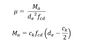
Step 1. Calculation of resultant moment, Ma
The resulting moment due to the design member force is calculated by Equation 3.12. The resultant moment is an initial value for calculating cko, which is the thickness of the minimum compression layer in Step2.
Equation 3.12
Ma = MEd - NEdeb
Equation 3.13
eb = de - t/2
Step 2. Calculation of 1st estimation of ck, cko.
The cko, which is the first estimation of ck from the resultant moment, is calculated according to the following equation 3.14.
Equation 3.14
Ck0 = de(1-√max[1.0 - 2µ, 0])
Where,
Step 3. Calculation of membrane force in compression layer.
By ck(or cko), the interlayer distance from the central axis is changed, as shown in Figure 24. Membrane force for the changed value is calculated by transforming Eq. 3.7 into Eq. 3.15.
Equation 3.15 (a)
NEdxk = NEdx(eb/a+MEdx/a)
Equation 3.15 (b)
NEdyk = NEdy(eb/a+MEdy/a)
Equation 3.15 (c)
NEdxyk = NEdxy(eb/a+MEdxy/a)
Step 4. Calculation of concrete normal design force in compression layer.
The concrete normal design force in the compression layer can be obtained from the equation in Table 8.
Step 5. Calculation of 2nd estimation of ck.
2nd estimation of ck is calculated by the following Equation 3.16.
Equation 3.16
Ck = Nconk/ƒcd
Step 6. Step3~5 is repeated.
If the nth ck and the n+1th ck match, the above process ends, and the last n+1 ck value is determined as the thickness of the final compression layer. The subsequent design process follows Table 5.
Design Considering the Location of Reinforcement
The above bending design processes assume that the reinforcing bar is located at the center of the assumed or estimated thickness of the outer layer. If the rebar position has a significant distance from the outer layer, it is necessary to recalculate the required amount of rebar by calculating the NReabri, taking this into account. The design value correction considering the position of the rebar is as follows.
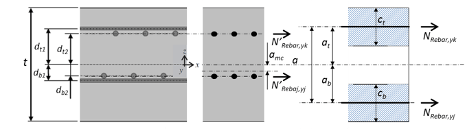
Step 1. Calculate the modified position of the section center (amc).
Equation 3.16
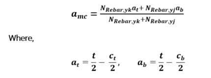
ct, cb in the optimal design state is the final layer thickness (ck) calculated according to Figure 23. Based on the center lines of amc, at and ab, the upper direction has a sign of (+), and the lower direction has a sign of (-).
Step 2. Calculate the modified NRebar,y ( N’Rebar,y).
The corresponding tension forces at each reinforcing bar level are calculated using the Equation below.
Equation 3.18 (a)
N'Rebar,yk = (NRebar,yk + NRebar,yj) * (amc - db2)/(dt2-db2)
Equation 3.18 (b)
N'Rebar,yj = (NRebar,yk + NRebar,yj) * (at2 - dmc)/(dt2-db2)
Step 3. Calculate the requested Rebar area (Areq,y).
The required reinforcement amount is calculated according to Equation 3.9.
Shear Design
Requirements
Shear resistance of the section (VRd) should be greater than the design shear force for the section (VEd). To satisfy Limit state of Shear Resistance the following condition should be met:
Equation 3.19
VEd ≤ VRd
Calculation of Shear Resistance (VRd)
The shear resistance of cell elements is being reviewed only for the shear resistance of concrete. So, it is applied as below.
Equation 3.20
VRd = VRd,c
For calculating the design shear resistance of concrete, larger of the following two values is adopted:
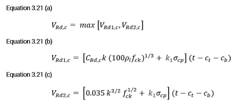 Where,
Asl is the area of the tensile reinforcement, which extends ≥ (lbd + d) beyond the section considered. For beam section, program considers Asl as the area of the tensile reinforcement provided. For column sections, the Asl is used as the Ast/2 i.e half of the area of the longitudinal reinforcement.
Refer to Appendix 1 for NEd calculation.
Calculation of Design Shear Force (VEd)
The design shear force of the cell element is considered the result of the design shear force of the two axes. So it is applied as below.
Equation 3.22
VEd = VEd0
The sum of shear forces can be calculated using the Equation below.
Equation 3.23
VEd0 = √V2Edx + V2Edy
Shell Design Tutorial
1. Shell Design Process
 (a) Full Model View
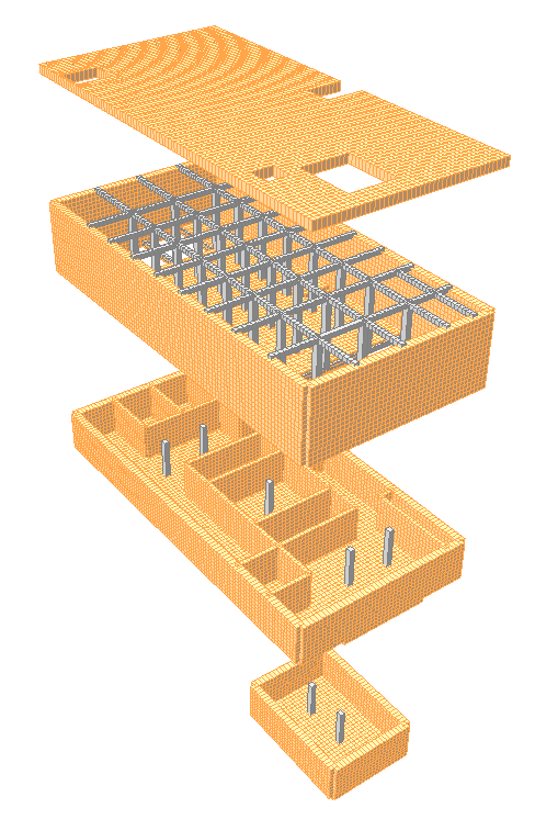 (b) Model View by Each Levels
Figure 26. Sample Model View
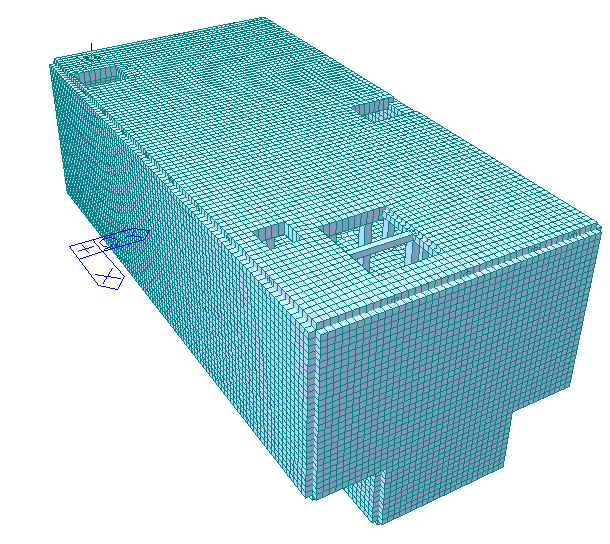
Step 1. Modeling by meshed plate
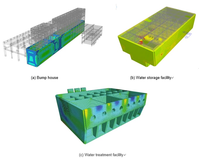
This sample is a water treatment facility installed underground. In the outer plate, the side load by earth pressure was input to the vertical wall, and the soil load was input to the horizontal slab.
Step 2. Modeling meshed plate
Distinguish the boundaries of the shell design. Reinforcement direction and reinforcement information are created for the divided area.
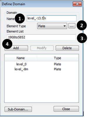
* Node/Element > Mesh > Define Domain
① Input Domain Name.
② Select Element Type as Plate.
③ Select Elements.
④ Click “Add”.
* Node/Element > Mesh > Define Domain
① Input Domain Name.
② Select Element Type as Plate.
③ Select Elements.
④ Click “Add”.
▶ Run “Analysis”.
Step 3. Generation of load combinations
Generate load combination information for shell design.
It can be automatically selected according to the code and can be modified or deleted by the user.
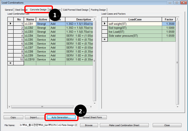
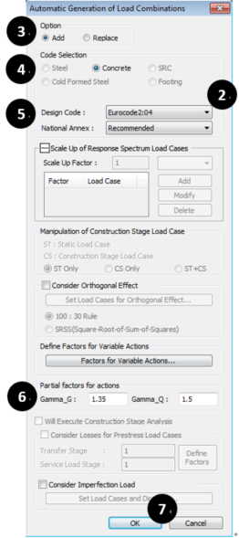
* Result > Combinations
① Click “Concrete Design” Tap.
② Click “Auto Generation” Button.
③ Option: “Add”.
④ Code Selection: “Concrete”.
⑤ Design Code: “Eurocode2:04”.
⑥ Input Values for Gamma_G and Gamma_Q.
⑦ Click “OK”.
Step 4. Setting load combination for shell design
Set load combinations for shell design. It is automatically generated by the load combination information created in Step3, and the user can select and cancel the load combination as needed.
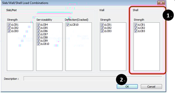
* Design > Design > meshed Design > Slab/Wall/Shell Load Combinations
① Select Load Combinations.
② Click “OK”.
Step 5: Setting design code and reinforcement ratio
Set design code and limit reinforcement ratio for shell design.
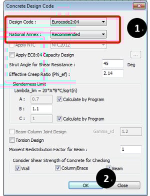
* Design > Design > RC Design > Concrete Design Code
① Select Design Code and National Annex.
② Click “OK”.
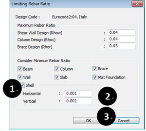
* Design > Design > RC Design > Limiting Rebar Ratio
① If consider Min Rebar ratio, Check this option.
② Default Ratio is 0.0013. and user can modify this value according to member type.
③ Click “OK”.
Step 6. Definition of shell design criteria for rebars and sandwich thickness
Define the diameter and spacing of the rebar used in the shell design and the distance from the shell surface to the rebar center. Also, input the information about the thickness of the out layer for applying the sandwich model.
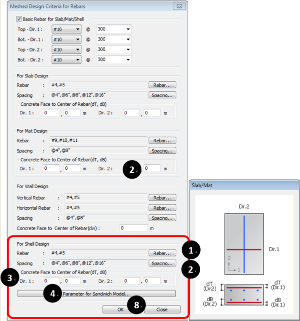
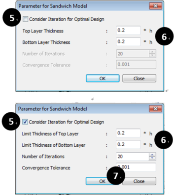 Figure 31b. Parameter for Sandwich Model Dialog Box
* Design > Design > meshed Design > Meshed Design Criteria for Rebars
① Click “Rebar…” and Select Rebar Size.
② Click “Spacing” and Select Rebar Spacing.
③ Input Concrete Face to Center of Rebar.
* If Values have 0, 0.065m will be inputted.
④ Click “Parameter for Sandwich Model…”.
⑤ If Optimal Design is applied, Check “Consider Iteration for…”.
⑥ Input Values of Sandwich Thickness.
When applying Optimal Design, Input Values of Limit Sandwich Thickness.
⑦ Click “OK”.
⑧ Click “OK".
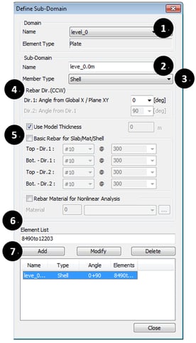
Step 7. Setting rebar information of shell flexural checking
Set rebar information for shell flexural checking. Rebar information can be entered by the following procedure.
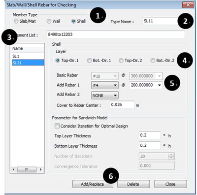
* Design > Design > meshed Design > Slab/Wall/Shell Rebar for Checking
① Member Type: Select “Shell”.
② Input Type Name.
③ Select Shell Elements.
④ Select Position and Direction for Rebar arrangement.
⑤ Define Basic Rebar and Add Rebar.
⑥ Click “Add/Replace”.
Step 8.1. Display of the detail report of shell flexural design
Display the Shell Flexural Design's detail report for all or selected elements.
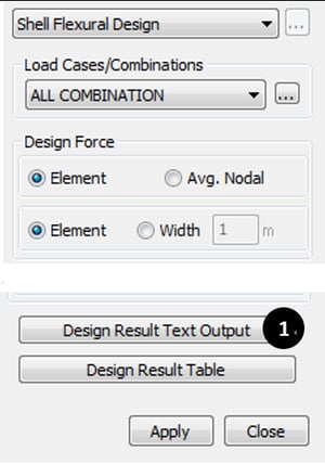
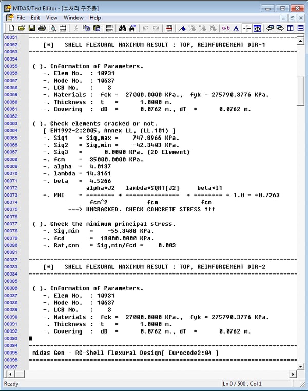 Figure 33a. Shell Flexural Design Dialog Box
* Design > Design > meshed Design > Shell Flexural Design
① Click “Design Result Text Output”.
Step 8.2. Display of the result of shell flexural design
Display the results of Shell Flexural Design.
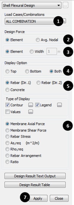
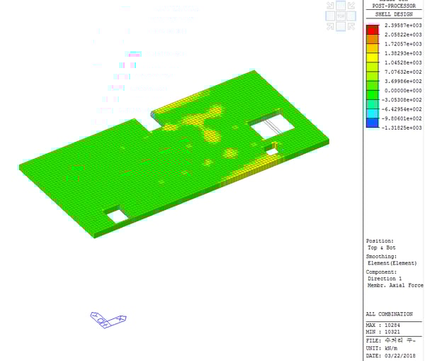
* Design > Design > Meshed Design > Shell Flexural Design
① Select Load Case or Load Combinations.
② Select Design Force Type.
③ When check “Width”, Input Width Value for Design Force Calculation.
④ Select Target Layer Position.
⑤ Select Target Item.
⑥ Select Target Result.
⑦ Click “Apply”.
Step 8.3. Display of the result of shell flexural design
Display the results of Shell Flexural Design in the table.
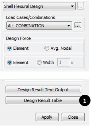

* Design > Design > Meshed Design > Shell Flexural Design
① Click “Design Result Table”.
Step 9. Performing the design review of input rebar
Perform the design review for the input rebar. It can be executed when reinforcing bar information is entered. Please refer to Step 7 for rebar input.
The type and method of checking results are the same as in Shell Flexural Design.
* Design > Design > meshed Design > Shell Flexural Checking
Step 10.1. Display of detail report of shell shear checking
Display Shell Shear Checking detail report for all or selected elements.
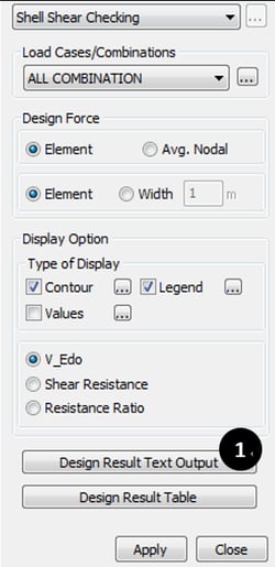
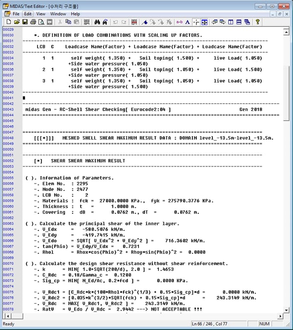
* Design > Design > meshed Design > Shell Shear Checking
① Click “Design Result Text Output”.
Step 10.2. Checking the result of shell shear checking
Check the results of Shell Shear Checking for all or selected elements in a table.
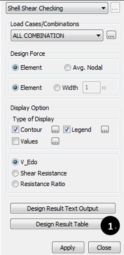
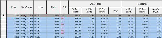
* Design > Design > meshed Design > Shell Shear Checking
① Click “Design Result Table”.
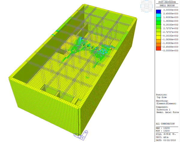
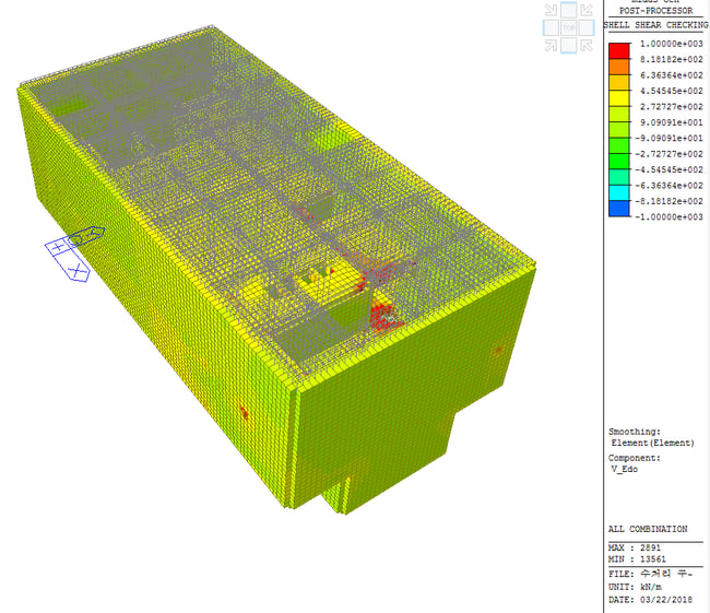
Step 10.3. Display of the result of shell shear checking
Display the results of Shell Shear Checking.
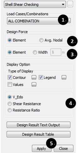
* Design > Design > meshed Design > Shell Shear Checking
① Select Load case or Load Combinations.
② Select Design Force Type.
③ When check “Width”, Input Width Value for Design Force Calculation.
④ Select Target Result.
⑤ Click “Apply”.
* Fill out the form below to download the full content *