 Banner Title Products
OVERVIEW
In small and medium-sized frame structures, very thin members such as angles and rod-bars are used for diagonal members or wind braces installed for structural stability or safety during construction. However, designing these slender members to resist compressive forces is very difficult and uneconomical. As a way to solve this problem, a method of performing a non-linear analysis that uses a tension-only element to limit the stiffness in the analysis is applied so that the elongated member does not resist the compressive force when performing structural analysis.
For nonlinear elements such as tension-only, compression-only, and cable, the load acting on the element or the stiffness matrix of the structural changes due to the displacement and member force generated according to the load during the iterative analysis process. Therefore, general load combination conditions that linearly combine analysis results for each unit load cannot be used.
In this case, the correct member force of nonlinear elements can be obtained only when the load combination conditions to be considered in the design are applied as a unit load condition for each analysis.
However, it is very difficult and cumbersome for the user to input the load every time to match the numerous load combination conditions. In this case, by using the 'Create Load Cases Using Load Combinations' function provided by midas Gen, the load to be considered in the load combination condition to be applied to the design can be easily entered as each unit load condition.
This document briefly introduces the functions related to Create Load Cases Using Load Combinations when some nonlinear elements are used in the structure, and explains the modeling and analysis process according to the procedure. In addition, the member force of non-linear elements by non-linear analysis was compared when the analysis results of the unit load condition were linearly combined and when the load combination condition was converted into a unit load condition load.
√Table of Contents
The structure of the main text is divided into two parts.
(1) Modeling and Analysis Considerations for Tension-Only Element Analysis
- ‘Create Load Cases Using Load Combinations’ function.
- Selection of convergence method when analyzing non-linear elements of Model Control Data.
- Check the convergence error condition in the Analysis Message window.
(2) Tension-only element modeling, structural analysis and design procedure using midas Gen
Modeling and Analysis Considerations for Tension-Only Element Analysis
The following are considerations to perform modeling and analysis of nonlinear elements.
1. ‘Create Load Cases Using Load Combinations’ function
- MidasGen supports the automatic conversion of a load combination including various load cases into a single static load case with a load factor applied.
The list of load combinations defined in the model is displayed, and the list of load combinations to be created as a unit load condition for nonlinear analysis is sent to the Selected Combinations list. The load condition created here can also be reflected as a load combination for use in design.
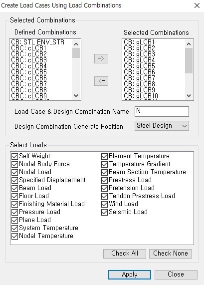
The Select Loads function automatically selects the type of load to be considered as a new unit load condition from among the loads reflected in the existing load combination conditions. If you click [Apply], all loads entered in the unit load conditions (DL, LL) constituting the load combination condition (CB:gLCB1) are reflected up to each load factor, and a new unit load condition (NgLCB1) is automatically created.
For reference, the tensile element can be applied to static analysis, nonlinear analysis (large deformation analysis), construction stage analysis, and PSC analysis. In other analyzes, truss elements are not replaced or nonlinear analysis is not performed. In particular, when performing seismic analysis, in eigenvalue analysis and response spectrum analysis, the tensile element is replaced by the truss element and compressive force may occur in the member, so please be careful when performing the analysis.
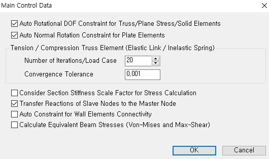
2. Selection of convergence method when analyzing non-linear elements of Model Control Data
- Before performing structural analysis, specify the convergence condition for nonlinear analysis in Analysis > Model Control Data.
- The number of Iterations/Load Case indicates the maximum number of iterations and Tolerance means the limit of convergence error.
3. Convergence Error Condition in the Analysis Message Window
- The analysis is performed according to the condition reached among two cases: the maximum number of iterations and the convergence error limit. Therefore, after the analysis is terminated, it is necessary to check whether the convergence condition specified in the Analysis Message window is satisfied. If the analysis is terminated due to the limitation of the number of iterations even though it has not converged, the reanalysis is performed by increasing the maximum number of iterations.
- The maximum number of iterations of the example is ‘20’, and the convergence error is ‘0.001’. Figure 3 shows the analysis message displayed on the Analysis Message window when performing nonlinear analysis.
- If you look at the message, it can be seen that the stiffness is reconstructed for each of the 24 existing load cases, and in the case of the 24th load case, the analysis is finished by satisfying the limit of convergence error in the 4th analysis without convergence until the 3rd analysis. it can be known that.
Here, 'Displacement Error Norm' indicates the degree of convergence of the analysis value based on the displacement during repeated analysis ({un } − {un−1}/{un }), and the convergence error specified by the user in Analysis > Main Control Data. If it is smaller than 'Convergence Tolerance', which is the limit of, it is judged that the analysis results in convergences.
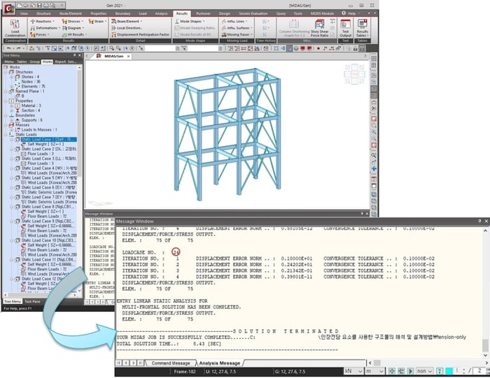 Figure 3. Nonlinear Analysis and Analysis Message
Nonlinear Element Modeling, Structural Analysis and Design Procedure using midas Gen
- In midas Gen, using the Load > Create Load Cases Using Load Combinations function, the design load combination condition can be easily replaced with a unit load condition, and all loads of the design load combination condition can be automatically entered as the unit load condition.
Here's how to apply many of the above-mentioned considerations to real-world models.
This model is based on the attached simple model.
(1) In File > Open Project, import the attached model tension-only(modeling).mgb.
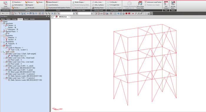 Figure 4. Example Model
(2) In Result > Combinations, create load combination conditions using the [Auto Generation] button.
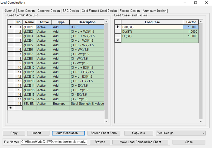 Figure 5. Create Load Combination Condition
(3) In Load > Create Load Cases Using Load Combinations, various loads included in the load combination conditions are automatically entered as 'unit load conditions'.
As mentioned above, in the analysis using non-linear elements such as tension-only, compression-only, and cable, this function is used because general load combination conditions that linearly combine the analysis results for each unit load cannot be used.
- In the 'Defined Combinations' list, select the list to be replaced with the nonlinear analysis unit load and press the arrow to move to the 'Selected Combinations' list.
- Add [N] to the 'Load Case & Design Combination Name' item to distinguish it from a linear load combination.
- Select [Steel Design] in 'Design Combination Generate Position' to use this load combination in design.
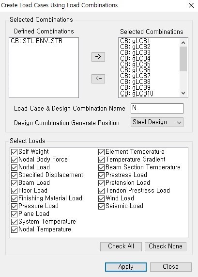 Figure 6. Changing the Load Applied to the Load Combination Condition to the Unit Load Condition
| General Comb. | Nonlinear Load Case | Steel Comb. | General Comb. | Nonlinear Load Case | Steel Comb. | ||||
| gLCB1 | NgLCB1 | NgLCB1 | gLCB10 | NgLCB10 | NgLCB10 | ||||
| gLCB2 | NgLCB2 | NgLCB2 | gLCB11 | NgLCB11 | NgLCB11 | ||||
| gLCB3 | NgLCB3 | NgLCB3 | gLCB12 | NgLCB12 | NgLCB12 | ||||
| gLCB4 | NgLCB4 | NgLCB4 | gLCB13 | NgLCB13 | NgLCB13 | ||||
| gLCB5 | NgLCB5 | NgLCB5 | gLCB14 | NgLCB14 | NgLCB14 | ||||
| gLCB6 | NgLCB6 | NgLCB6 | gLCB15 | NgLCB15 | NgLCB15 | ||||
| gLCB7 | NgLCB7 | NgLCB7 | gLCB16 | NgLCB16 | NgLCB16 | ||||
| gLCB8 | NgLCB8 | NgLCB8 | gLCB17 | NgLCB17 | NgLCB17 | ||||
| gLCB9 | NgLCB9 | NgLCB9 |
Table 1. Changed Load Combination Condition to Nonlinear Unit Load Condition, and Changed Nonlinear Unit Load Condition to Design Load Combination Condition
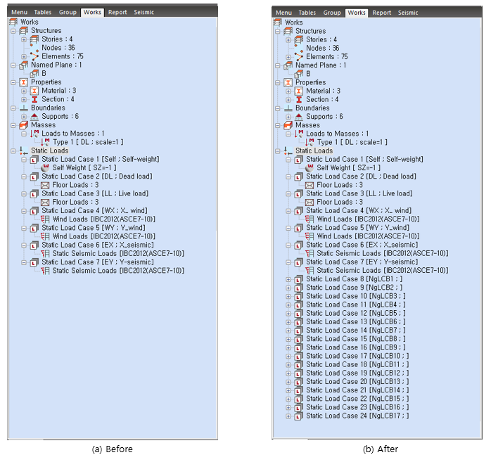 Figure 7. Work Tree Before and After Using Create Load Cases Using Combinations Function
(4) In Analysis > Main Control Data, specify the nonlinear analysis condition and the convergence condition.
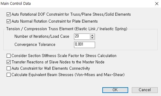 Figure 8. Analysis and Convergence Conditions
(5) In Analysis >Perform Analysis, the analysis is performed.
- When the analysis is terminated, check the convergence in the Analysis Message window, and if the convergence is not appropriate, increase the maximum number of iterations and perform re-analysis until the convergence error is reached.
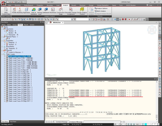 Figure 9. Analysis Message Window When Performing Nonlinear Analysis
(6) In Result > Deformation > Deformed Shape, comparing the non-linear analysis and the linear analysis of the lateral displacement of the top layer, the non-linear analysis, where the brace member is interpreted as a tension-only element and receives only tensile force, has a higher lateral displacement than the linear analysis of the truss element that resists lateral force while receiving compressive force. You can see more increase.
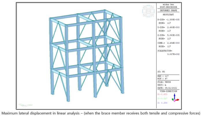
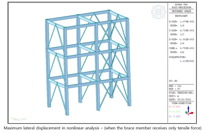 Figure 10. Comparison of Maximum Lateral Displacement
(7) In Result > Forces > Truss Forces, check the member force of the tension-only element. Since the element exclusively for tension is used, it can be confirmed (‘0.3 kN’) that almost no member force is generated by repeated analysis of the member that must bear the compressive force.
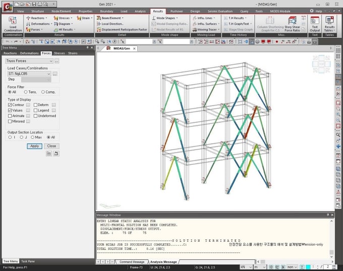 Figure 11. Checking the Member Force of the Tension-Only Element
If you look at the member force of the tensile element under the unit load condition (ST:NgLCB5), it is different from the case where the results are analyzed for each unit load condition and the results are linearly combined (CB:gLCB5).
In the case of a linear combination, it can be confirmed that compressive force is generated in the member even if non-linear analysis is performed. In addition, in the case of the unit load condition (ST:NgLCB1) that combines the gravity load, only the compressive force is received. In the case of the unit load condition including the lateral load (ST:NgLCB3), there is no member force in the brake with the exclusive tensile element. creates a tensile force.
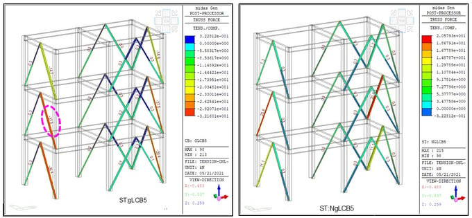 Figure 12. Comparison of Member Force with Linear Combination (gLCB5) and Nonlinear Unit Load Condition (NgLCB5)
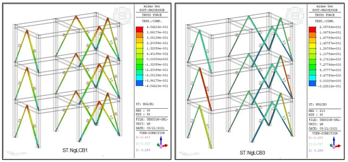
To summarize the following results, when non-linear elements are used in the linear system, it is not appropriate to linearly combine the analysis results of the unit load conditions. Using the 'Create Load Cases Using Load Combinations' function, the 'Load Combination Conditions for Design' After substituting 'unit load condition', the boundary nonlinear analysis result for the unit load condition should be applied to the design.
(8) Check that the load combination for design has been created in the Result > Load Combinations >Steel Design tab.
- When creating Load Cases Using Load Combinations, load combinations for design are created at the same time in the selected tab, so it is very convenient because it does not create a load combination for design separately.
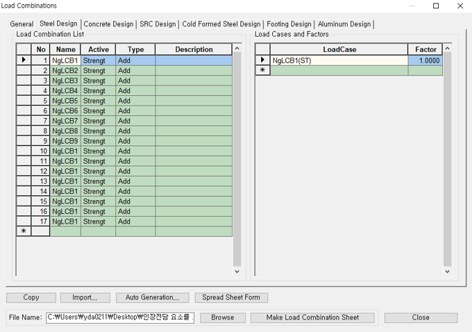 Figure 14. Creating Load Combinations for Design
(9) When designing a member, you must design a tensile-only element using a load combination (Steel Design > NgLCB1 to NgLCB17) applied with a load group for nonlinear analysis (NgLCB1 to NgLCB17).
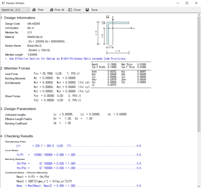 Figure 15. Design Results of Tension-Only Elements
If the static analysis is performed with the truss element, it can be confirmed that the non-linear analysis described so far is OK even for the members that generate NG.
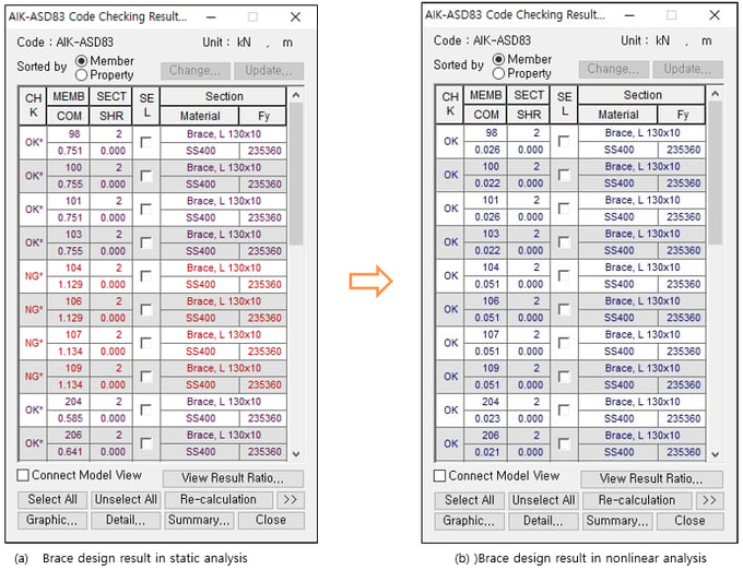 Figure 16. Comparison of Brace Member Design Results According to Linear and Non-Linear Analysis
Also, it can be seen that the axial force generated from the brace is transferred to the main frame, and the main frame member force is increased.
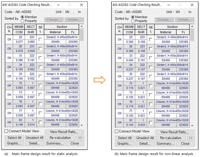 Figure 17. Comparison of Main Frame Member Design Results for Linear Analysis and Nonlinear Analysis
Conclusion
In the nonlinear analysis using the tension-only element, it is repeated so that the compressive force does not occur by reducing the stiffness of the tensile element receiving the compressive force or canceling the load for the load in which the load combination, not the elastic load combination, is replaced with a unit load. Perform analysis.
If you model and analyze using the function for tension-only element analysis, the analysis result is compared with the linear analysis result applied with the same section, and it can be confirmed that the brace member in which NG occurred is OK. It can also be seen that the member force of the mainframe and the maximum lateral displacement is slightly increased. As such, there is no compressive force on the tension-only elements, so it is possible to obtain analysis results that accurately reflect the applied load.