 Banner Title Products
Structure in 2-Way Slab System
The Building Structural Standard defines a two-way slab system as a concrete slab system in which two rebars are arranged in two directions regardless of the presence or absence of a beam that transmits a load to a column'. Also, in ACI 318, this is expressed as ‘slab systems reinforce flexure in more than one direction, with or without beams between supports’. Therefore, a two-way slab system refers to a slab system in which reinforcing bars are arranged for bending in two or more directions regardless of the presence or absence of beams in columnar rows'. Typical types of two-way slab systems commonly used today include two-way slabs with beams, flat plates, flat slabs, and waffle slabs.
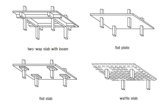
Figure1. Typical Types of 2-Way Slab
The Concept of 2-Way Slab Sytems
1) Two Way Slab with Beam
Beams are placed along the edge of the slab plate, and columns are installed at the edge of the plate to support the slab and beam. The system is called a two-way slab with beams. (Shown in Figure 1) In this system, if the ratio of the long side to the short side of the slab plate is two or more, the transfer of h is mainly made by bending in the short side direction, so it is called a one-way slab. On the other hand, as the ratio of the long side to the short side gradually decreases to 2 or less, The load transfer due to bending in the short side direction decreases, and the load transmission by bending in the long side direction increases, resulting in a two-way slab in which the load is transmitted by bending in the two directions.
2) Flat Plate
With the development of structural engineering technology, the main column began to gradually disappear from the two-way slab with beams that have been used for a long time. As a result, a flat plate, in which the column directly supports the slab plate without a main column, appears. The flat plate is a very efficient and economical two-way system, and it has become a slab system widely applied to multi-story buildings such as apartments, condos, dormitories, hotels, and hospitals. The flat plate is a floor structure system consisting of the simplest formwork shape and rebar arrangement, and has the advantage of being able to construct with a shorter period of time and less labor cost than any other floor structure system. In addition, flat plates have many advantages in terms of architectural planning. For example, because the floor structure is thin, the floor height is low, so the heights of external curtain walls, internal partition walls, elevators and stairs, equipment ducts and piping, etc. are reduced. The volume of the building is reduced, so the heating and cooling load is also reduced. In particular, in buildings with height restrictions, it will be possible to plan more floors at a limited height by lowering the floor height. In addition, the flat plate is a highly flexible floor structure system in which columns, partition walls, small openings, and the like can be freely arranged. The flat plate has the disadvantage that the slab is the thickest floor structure due to structural requirements such as shear and deflection. However, thick slabs also have the advantage of improving fire resistance and reducing noise between floors.
3) Flat Slab
One of the factors limiting the use of flat plates is excessive thickness caused by 2-way shear around the column. For flat plates with a large load or long span, the required thickness around the column due to two-way shear is large, resulting in a large overall slab thickness. In this case, as shown in Figure 1, there is a method of reinforcing only the slab around the column by partially increasing the thickness, which is called a drop panel or shear cap. A slab system in which a flat plate is reinforced with a fingerboard or shear plate in this way is called a flat slab. Sometimes, for the same reason as the fingerboard, a column head with the upper part of the column raised in the shape of a trumpet as shown in Figure 1 is used. For the convenience of design, the fingerboard is considered a part of the slab, and the column head is considered a part of the column. The flat slab has the advantage of reducing the fixed load as the amount of concrete is reduced while the formwork is slightly more complicated than the flat plate. Flat slabs, like flat plates, have a low floor height, so they have various advantages. In this way, flat plates and flat slabs that columns directly support the slab without installing main column beams are called ‘two-way slab without beam’.
4) Waffle Slab
The waffle slab is a two-way joist structure consisting of a concrete joist arranged orthogonally in 2 directions as shown in figure 1 and a solid head around a column. In general, two-way concrete joists can be made using an orthogonal dome-type formwork, and in order to increase shear strength, the part corresponding to the ground board around the column is treated as a plate without installing a joist. For convenience, the waffle slab is a floor structure system that is particularly useful in floor structures that require a thick slab due to a long span or a large load because the waffle slab considers the whole plate as a fingerboard and significantly reduces the fixed load compared to the flat slab. Sometimes, the lower part of the waffle slab is exposed to express the geometric beauty of the two-way concrete joists.
Range of Application
The direct design method and the equivalent frame method, the two-way slab design methods explicitly stipulated in the standard, are based on the results obtained by analyzing the performance records of various slab systems and a series of extensive experiments. As it is about the reinforcement of the flexural reinforcement, in order to secure the stability of the slab system, the requirements for load transfer between the slab and the column by bending, torsion, and shear should be considered separately.
The basic design principles for standard two-way slabs can be applied to all flat plate structures to which out-of-plane loads are applied, but certain types of slabs are limited in applying the direct design method or equivalent framing method. Common two-way slab system types to which direct design method or equivalent frame method can be applied include two-way slab with beams, flat plate flat slab, and waffle slab.
A slab whose supporting condition is essentially one-way or a slab with reinforcing bars arranged to resist bending in only one direction is not included in the category of two-way slabs. Also, ground slabs are excluded from this category unless they receive the vertical load of other structural members and transfer it to the ground.
In a slab with beams, the direct design method or equivalent framing method can be applied only when the beam is placed along the edge of the slab plate and the beam and the slab are supported by placing columns or supports without deflection at the edge of the slab plate.
That is, the direct design method or equivalent framing method cannot be applied to a two-way slab that supports the slab with intermediate beams in one direction and supports the slab and intermediate beams with main girders in the other direction. Even in this case, it can be designed by applying the general requirements of the standard, but the design should be based on structural analysis considering the suitability for the deflection of the intermediate beams and main girders supporting the slab.
In the case of a slab supported by a wall, the wall is considered as a beam with infinite stiffness in the direct design method or the equivalent frame method. Therefore, in this case, the wall should be installed over the entire length of the edge of the slab. A wall shorter than the edge of the slab can be regarded as a column and designed by a direct design method or equivalent framing method.
Design Method
2-way slab system can be designed in any way if it is fulfilled the requirements of the standard of usage and stiffness. It can also be analyzed by the design method specified in the standard, the direct design method (DDM) or the equivalent frame method (EFM), or it can be designed based on the structural analysis in which the basic principles of structural mechanics are directly applied. However, the design of the two-way slab system should not rely solely on structural analysis. If the physical dimensions of the slab deviate from common practice, it should be justified on the basis of accurate information on the expected loads and confidence in the stresses and deformations of the structure.
1) Structural Analysis for Vertical Load
There are direct design and equivalent frame methods in the analysis method about the vertical load specified in the standard. The direct design method is an approximate analysis method to obtain the bending moment using the moment coefficient, and the equivalent frame method is a more accurate analysis method to get the bending moment through elastic analysis. Although the direct design method is an approximate analysis method, it is a method that can reasonably obtain the bending moment on the safety side within the application limiting conditions.
The direct design and equivalent frame methods can be applied only to structures in which columns or walls are basically arranged at right angles. Since these design methods can be applied regardless of the presence or absence of main column beams, they can be applied to the design of two-way slabs with beams, flat plates, flat plates such as flat slabs, and waffle slabs. It should be noted here that none of these design methods can be applied to a floor structure system in which large beams support small beams.
In other words, these design methods can be applied only when all beams are arranged along the column row and the beam and the slab are supported by installing columns or supports without deflection at all corners of the slab plate. Of course, it is also possible to design based on structural analysis in which the basic principles of structural mechanics of all floor structures are directly applied regardless of the suitability of the application conditions for these two design methods.
2) Structural Analysis for Lateral Load
During the life cycle of a structure, cracks occur in the slab due to bending by construction load, normal occupied load, and expected excess load, and volume change by drying shrinkage and temperature change. In lateral load analysis, the stiffness of the slab in consideration of cracks should be used to prevent underestimation of the lateral displacement of the structure due to wind or seismic loads. The structural analysis for the lateral load can use any analysis model based on an approximate solution that satisfies the force balance condition and geometrical fit condition, but the result must be reasonably consistent with the test data.
The analysis model should be able to consider the effects of not only cracks in the slab, but also the aspect ratio of the slab plate (l2/l1), the ratio of the slab span and the length of the column (c1/l2), and the aspect ratio of the column cross-section (c2/c1). For available approximate solutions, there are plate-bending finite-element model, effective beam width model, and equivalent frame model, the member stiffness should be reduced by considering cracks in any cases.
The flexural stiffness of the reinforced concrete slab is generally assumed to be between 25% and 50% of the flexural stiffness of the non-cracked section.
General Information
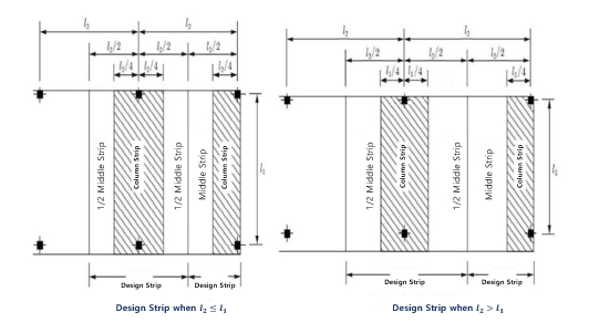
1) Design Strip
The two-way slab analyzes the standard of the design strip divided by the column centerline, and divides each design strip into a column strip and a middle strip to distribute the bending moment of the design strip in a predetermined ratio.
The column strip is a design strip with the smaller value between 0.25l2 and 0.25l1 on either side of the column centerline as the width on one side. Since the width of the column strip is likely to be changed if the span changes along the design bench, it should be properly designed and adjusted. The reason why the span has a standard of the smaller value among l1 and l2 is that the bending moment tends to be concentrated near the main column if it is smaller than the width of the slab.
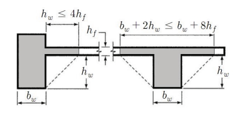
2) Effective Section of Beam
When a slab and a column are integral or fully composite structures, the cross-section of the beam includes a certain part of the slab as a flange, as shown in Figure 3. The extruded width of the flange shall be the greater value of the depth at which the beam is extruded above or below the slab, and should not exceed 4 times the slab thickness. The design constant and stiffness used in the direct design method or equivalent frame method should be obtained from this effective cross-section.
3) Beam-Slab Stiffness Ratio
‘Beam-Slab Stiffness Ratio’, α, refers to a ratio of the bending stiffness of the beam by the bending stiffness of the slab in the same design. At this time, the bending stiffness of the slab is calculated with respect to the effective cross-section of the beam over the entire width of the design strip. The beam-slab stiffness ratio is a design constant used for conditions for calculating the minimum thickness of the slab, the application condition of the direct design method, and the calculation of the bending moment distribution ratio for the main column. The beam-slab stiffness ratio is generally expressed as α1 for the span direction and α2 for the direction perpendicular to the span.
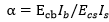
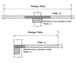
Figure 4. Beam-Slab Stiffness Ratio, α
4) Drop Panel and Column Capital
In order to reduce the amount of reinforcing bars against the negative moment of the upper part of the column in a flat slab or to increase the shear strength of the slab around the column or to apply the minimum thickness that does not need to consider deflection, the drop panel should be installed with a defined size from the standard like as Figure 5 (1). A column capital can be installed smaller than the drop panel only to increase the shear strength, as shown in Figure 5 (2). For the slab that installs drop panel or the column capital, it should consider not only around the column but also shear strength around them. When estimating the rebar amount of the slab in the drop panel, the thickness of the drop panel under the slab is to be taken as less than 1/4 of the distance from the edge of the drop panel to the face of the column or the face of the column head.
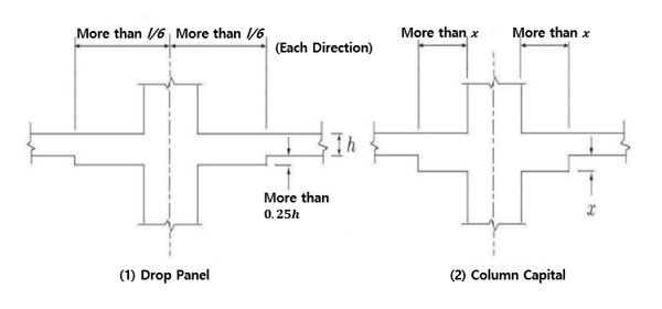 Figure 5. Drop Panel and Column Capital
5) The Minimum Thickness of the Slab
In the standard, the minimum thickness of a two-way slab is set, so that the slab thickness can be determined without geographical and complicated deflection calculations. This minimum thickness is applied to the slab whose long side to short side ratio of the slab (β) is 2 or less. When using a thinner thickness than this, the deflection shall be calculated and it shall be confirmed that the deflection is less than the allowable deflection of the standard.
The Minimum Thickness of a Flat Slab
Table 1 is a translation of the standard table, and the minimum thickness is calculated by applying it to a slab without a beam inside, such as a flat plate, flat slab, and waffle slab. Even if there is a beam around the slab, this table should be applied when the average beam-slab stiffness ratio (αm) is 0.2 or less. When it comes to ‘With Drop Panel’ in table 1, it means the case of setting the drop panel more than the required size in the standard), it has to be considered as ‘Without Drop Panel’ if it is installed less than that. It should be noted that even if a drop panel larger than the size required by the standard is installed to increase the shear strength, the minimum thickness cannot be reduced. 'Case with edge beam' refers to the case of installing edge beams with a beam-slab stiffness ratio of 0.8 or more, and a beam of a normal size has a beam-slab stiffness ratio of 0.8 or more. The minimum thickness for a slab without a drop panel is 120mm, and for a slab with a drop panel, 100mm is the minimum thickness.
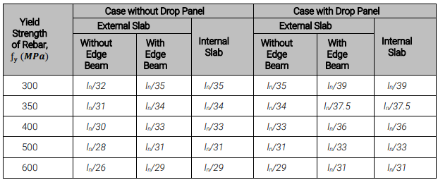 Table 1. The Minimum Thickness of a Flat Slab
The Minimum Thickness of 2-Way Slab with a Beam
The minimum thickness of a 2-way slab with a beam is applied when an average beam-slab stiffness ratio (αm) of the beam around the slab is exceeding 2, the minimum thickness is calculated depending on the standard, as follows. The value of β is a ratio of the long side for the cross-section of the slab plate.
(1) When the average ratio of beam-slab stiffness is 0.2<αm<2.0,
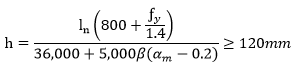
(2) When the average ratio of beam slab stiffness is 2.0 ≤ αm
(3) For external slabs, edge beams with a beam-slab stiffness ratio (α) of 0.8 or more should be installed or the minimum thickness obtained from formulas above should be increased by 10% or more.
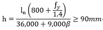
Table 2 shows the minimum thickness of a two-way slab with beams according to the beam-slab stiffness ratio of edge beams (α), average beam-slab stiffness ratio of peripheral beams (αm), and the ratio of the long side to the short side of slab plate (β).
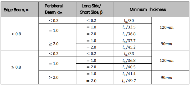 Table 2. The Minimum Thickness of 2-Way Slab with a Beam – External Slab (ƒy = 400MPa)
Arrangement of Slab
1) Minimum Rebar Amount and Maximum Span of Bending Bar
Minimum Rebar Amount of Bending Bar
The amount of reinforcing bars for two-way slabs must be greater than the amount of reinforcing bars required for shrinkage warm-rolled rebar. That is, rebars with a design standard yield strength of 400 MPa or less should be arranged with 0.002 bh or more, and for rebars with 500 MPa rebars with a design standard yield strength of less than 0.016 bh. (b=slab width, h=slab thickness)
Maximum Spacing of Bending Bar
The maximum spacing limit for bending rebars is a provision to prevent cracks in the slab and the possibility of concentrated loads acting on narrow sections. Our standard stipulates that the bending reinforcing bars of a two-way slab should be reinforced with a thickness of not more than twice the thickness of the slab and not more than 300mm only in the hazardous section, and the maximum spacing is not stipulated for other sections. However, it should be noted that, in ACI318-14, the maximum spacing is limited to not more than twice the slab thickness and less than 450mm (dangerous section), and 3 times the slab thickness and less than or equal to 450mm (section other than the dangerous section).
2) Development and Splice of Bending Bar
In the case that a two-way slab is supported by edge beams, columns, or walls at the edge, positive and negative moment rebar perpendicular to the edge shall be fixed as follows.
Positive Moment Rebar at Discontinuous End
The positive moment rebars at the discontinuous end orthogonal to the edge of the slab shall extend to the edge and be buried at least150mm or more from the supporting part of the edge beam, column, or wall with a straight line or hook. (Figure 6, 7, and 8)
Negative Moment Rebar at Discontinuous End
Negative moment rebars with discontinuous ends perpendicular to the edge of the slab are to be fixed on the supporting surface of the frame beam, column, or wall by bending, hooking, or other methods.
Rebar Detail of Flat Slab
- Reinforcing bars of flat slabs and flat plates, etc., should follow the minimum extension length according to Fig. 6 in addition to the general 2-way slab reinforcement rules.
- If the lengths of adjacent spans are different, the extension length of the negative moment rebar in Fig. 6 shall be calculated from the length of the longer span.
Figure 6. Development, Splice, and Minimum Extension-Length of Flat Slab
- If a flat slab is included in the frame supporting the lateral force, the extension length of the rebar is likely to be longer than the length shown in Fig. 6 due to the combination of the lateral force and the vertical load, so this should be confirmed by structural analysis.
- All lower rebars of the main column shall be continuous or have class A tension splices in the area shown in Fig6. In the drawing of the standard, this regulation is expressed as "In this area, it must be a class A joint", this is a bit of an immature expression, it has to be amended as "Tension splices are allowed only in this area, and class A tension splices shall be used". This is because the meaning of "In this area, it must be a class A joint" can be interpreted as allowing joints (such as class b joints) in other areas. In addition, this clause should be noted that it is reinforced with class B tensioning in ACI318-14 (from ACI318-08) as follows and includes fully mechanical and fully welded splices.
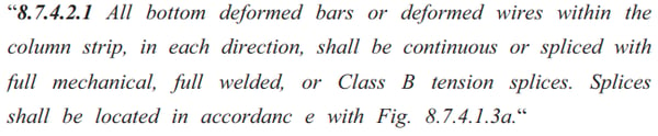
* In this clause, ‘Fig. 8.7.4.1.3a’ is identical to Figure 6.
- Two or more rebars among all bottom rebars of the column strip must pass between the main bars of the column, it should be developed more than the required development length in the external pedestal.
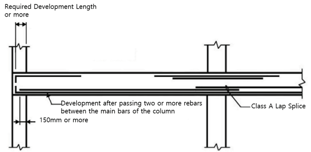
Figure 7. Development and Splice of Column Strip Rebar of Flat Slab
Figure 8. Development and Splice of Middle Strip Rebar of Flat Slab