 Banner Title Products
Moment Redistribution Coefficient
In RC structures, the yielding of one member does not result in collapse of the structure. This is because there is a significant extra strength between the yield and collapse status of the first member.
That is, when a member reaches its ultimate moment, it does not reach a failure status. At the cross-sectional location where a large moment occurs, plastic hinges occur first before failure. At this time, a change in the moment distribution of the beam occurs due to a decrease in the section stiffness.
This phenomenon is a redistribution of moment.
A reasonable evaluation of member strength is very important to consider moment redistribution. By designing according to the redistributed moment, it is possible to reduce the reinforcing bars at the ends, thereby relieving the overcrowding of rebars in places with large moments, such as the joints of columns and beams. This means you can proceed with a more economical design.
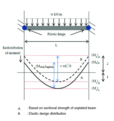 Figure 1. Redistribution of Moment
2. Procedure as per ACI318M-14
3. Example (by manual) : How to calculate a redistributed moment
4. Example (by manual) : How to calculate a moment redistribution factor as per ACI318M-14
5. How to Apply Factors to nGen
6. Application in Practice
Relevant Code : ACI 318N-14 & EN1992-1-1 : 2004
Calculation of Moment Redistribution Coefficient by Each Design Code : ACI318N-14
A calculation method of moment redistribution coefficient and restriction in each design code will be introduced.
The first code is ACI 318.
The applied model is a continuous flexural member and has a strain in the tensile part which is 0.0075 or more.
But, the redistribution factor cannot exceed 1000εt and 20%.
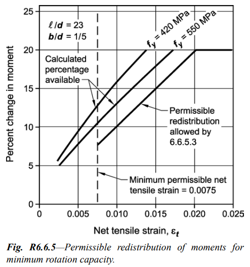 Figure 2. Permissible Redistribution of Moments for Minimum Rotation Capacity
 Figure 3. Redistribution of Moments in Continuous Flexural Members
Calculation of Moment Redistribution Coefficient by Each Design Code : EN1992-1-1 : 2004
The next is a regulation of moment redistribution in Eurocode.
A continuous beam and slab identical to ACI are target, the factor of the lengths of adjacent span should be in the range of 0.5 to 2.
The calculation of moment redistribution coefficient follows the equation as shown in 5.10.
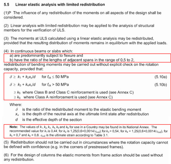 Figure 4. Linear Elastic Analysis with Limited Redistribution
Procedure as per ACI318M-14
It specifically explains the moment redistribution depending on ACI.
This graph is a procedure for the application of moment distribution according to ACI318M-14.
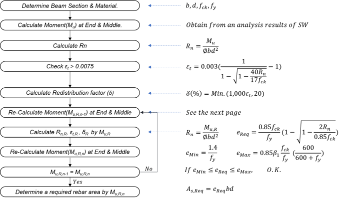 Figure 5. Procedure as per ACI318M-14
Example (by manual) : How to calculate a redistributed moment
When the moment redistribution coefficient assumes to be 0.2, this table indicates how to calculate the value of the redistributed bending moment and the bending moment considering redistribution depending on the location of each member.
See each equation carefully. (equations of the redistributed moment are different depending on the location.)
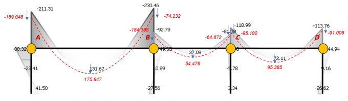 Figure 6. Moment Redistribution Example Model
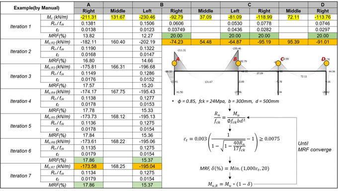
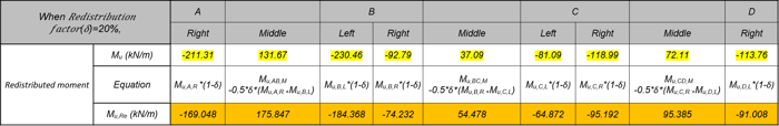 Table 1. Moment Redistribution Calculation by Manual
Example (by manual) : How to calculate a moment redistribution factor as per ACI318M-14
The procedure should be continued until the moment redistribution coefficient is converged as the example.
How to Apply Factors to nGen
This is a “redistribution coefficient input” in an actual MIDAS program. It shows the order to input data by applying the value of the redistribution coefficient yielded from the previous equation.
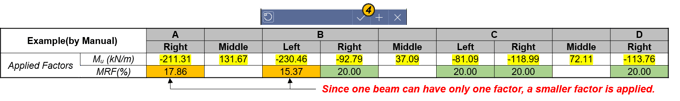
Since each beam can have only one factor, a smaller factor is applied.
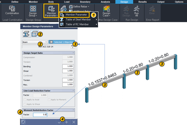
① Click “Member Parameter”.
② Select a material and member type.
③ Select target members on the modeling window.
④ Input the moment redistribution factor
(Factor = 1 – MRF)
⑤ Click “V” button.
The below is a result of yielding the design moment (redistributed moment) depending on the redistributed coefficient inputted in the program.
It should be noted that the result value is different from the value calculated by the previous equation, due to the constraint for the redistribution coefficient input.
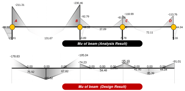
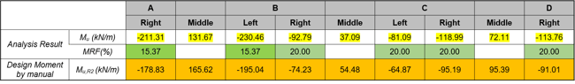 Figure 9. Analysis and Design Result
Application in Practice
How to consider a moment redistribution to practices without calculating the factor
To calculate and apply MRF for all beams is time-consuming. Therefore, it may be applied as follows without MRF calculation.
- For the end moment, the analysis result is used in the design as it is.
- For the middle moment, the moment value increased by 20% of the end moment is used in the design.
- The design ratio should be set to 1.00 as much as possible.
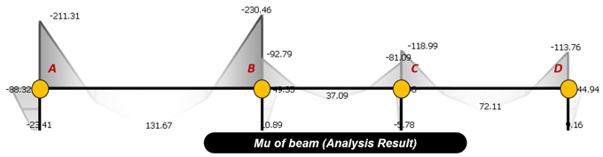
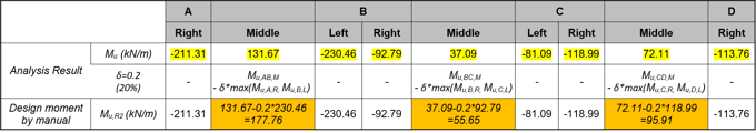 Figure 10. Application Way without MRF