 Banner Title Products
What is it? - Deflection Limitation
The beam deflection is one of the checks that should be performed for serviceability limit state design. Deflection is the displacement within a structural member under the influence of loads, ignoring the displacements of the rest of the structure.
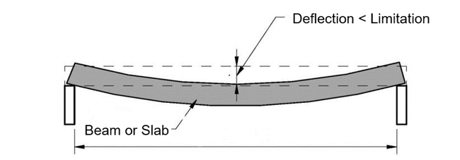 Figure 1. Deflection Limitation
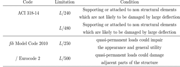 Figure 2. Suggested Deflection Limits for Structural Elements
Calculation of Stiffness Center
How to calculate it? (Comparison of Analysis Result & Design Result)
SW does not simply use analysis results because the deflection in the analysis result is a value including the deformation of adjacent members.
Design result of the cantilever beam
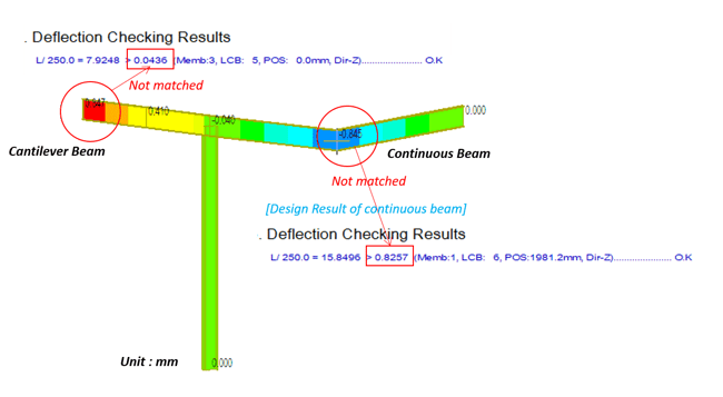 Figure 3. Deflection Checking Results
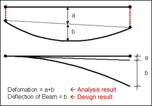
How to calculate it by manual? (Example - Cantilever)
Calculation by manual gives an approximate value, so manual value and Gen result value cannot be matched.
Please refer only to the calculating concept and way.
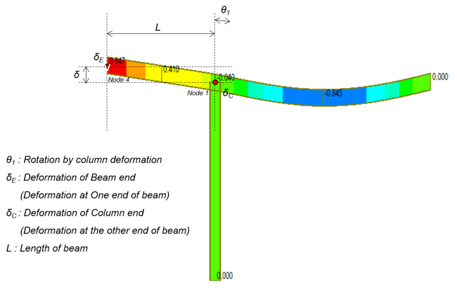 Figure 5. Cantilever Example Model
How to calculate the deformation of the cantilever by manual (unit : mm) - Example
δ = (δE –δC ) – θ1 *L (add this to remove the effect by column deformation)
= (0.846566 – (-0.039507)) – 0.000473* 1981.2
= -0.0510 mm
Deflection checking results
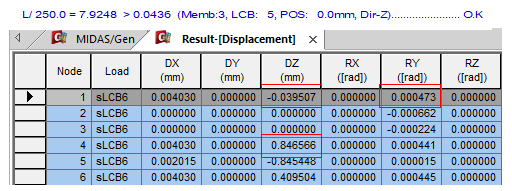 Figure 6. Deflection Checking Results - 1
How to calculate it through Gen? (Example - Cantilever)
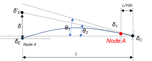
θ1 : Rotation by column deformation
θ2 : The angle of the line that links the deformed points of the
beam-column joint and of first node when L is divided into
100 equal parts.
δE : Deformation of Beam end (Deformation at One end of beam)
δC : Deformation of Column end (Deformation at the other end of
beam)
Node A : the first internal node when L is divided into 100 equal
parts
L : Length of beam
How to calculate deformation of the cantilever in midas Gen (unit : mm)
Gen uses θ2 calculated internally. θ2 means the angle of the line connecting the nodes of the column and the deformed node closest to the column when the beam is divided into 100 equal parts and
θ2 = (Dz at node A = Dz at Node 1 ) / (L/100)
= (-0.031082 – (-0.039507)) / (1981.2/100)
= 0.000425
δ = (δE –δC ) –θ2 *L
= (0.846566 – (-0.039507)) – 0.000425* 1981.2
= - 0.0436 mm
Deflection checking results
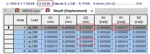 Figure 6. Deflection Checking Results - 1
Dz at Node A = -0.031082
Since this is an internal value, it is not output separately.
How to calculate it? (Example -Continous Beam)
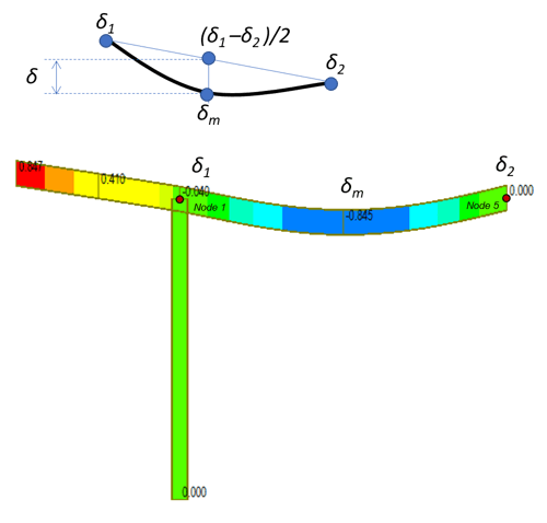 Figure 8. Continuous Beam Example Model
δ1 : Deformation at One end of beam
δ2 : Deformation at the other end of beam
δm : Deformation at middle point of beam
How to calculate the deformation of the cantilever by manual (unit : mm)
δ = δm – (δ1 –δ2 )/2
= 0.845448 – (0.039507 – 0.000) / 2
= 0.8257 mm
Deflection checking results
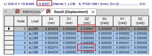 Figure 9. Deflection Checking Results -2