 Banner Title Products
Introduction
The success of a structural analysis very much depends on how closely the selected elements and modeling represent the real structure. Analysis objectives determine the selection of elements and the extent of modeling. For example, if the analysis is carried out for the purpose of design, then the structure needs to be divided into appropriate nodes and elements in order to obtain displacements, member forces and stresses that are required for design.
It would be more efficient to select elements so that the member forces and stresses can be used directly for design without subsequent transformation. A comparatively coarse mesh model may be sufficient to obtain displacements or to perform eigenvalue analysis. In contrast, the model with fine mesh is more appropriate for computing element forces.
In the case of an eigenvalue analysis where the prime purpose is to observe the overall behavior of the structure, a simple model is preferable so as to avoid the occurrence of local modes. At times, idealizing the structure with beam elements having equivalent stiffness works better than a detailed model, especially in the preliminary design phase.
Important considerations for creating an analysis model are outlined below. Some of the factors to be considered for locating nodes in a structural model include the geometric shape of the structure, materials, section shapes and loading conditions. Nodes should be placed at the following locations:
- Points where analysis results are required
- Points where loads are applied
- Points or boundaries where stiffness (section or thickness) changes
- Points or boundaries where material properties change
- Points or boundaries where stress concentrations are anticipated such as in the vicinity of an opening
- At the structural boundaries
- Points or boundaries where structural configurations change
When line elements (truss elements, beam elements, etc.) are used, analysis results are not affected by the sizes of elements. Whereas, analyses using planar elements (plane stress elements, plane strain elements, axisymmetric elements and plate elements) or solid elements are heavily influenced by the sizes, shapes and arrangements of elements.
Planar or solid elements should be sufficiently refined at the regions where stresses are expected to vary significantly or where detailed results are required. It is recommended that the elements be divided following the anticipated stress contour lines or stress distribution.
Fine mesh generations are generally required at the following locations:
- Regions of geometric discontinuity or in the vicinity of an opening
- Regions where applied loadings vary significantly; e.g. points adjacent to relatively large magnitude concentrated loads are applied
- Regions where stiffness or material properties change
- Regions of irregular boundaries
- Regions where stress concentration is anticipated
- Regions where detailed results of element forces or stresses are required
The factors to be considered for determining the sizes and shapes of elements are as follows:
- The shapes and sizes of elements should be as uniform as possible.
- Logarithmic configurations should be used where element size changes are necessary.
- Size variations between adjacent elements should be kept to less than 1/2.
- 4-Node planar elements or 8-node solid elements are used for stress calculations. An aspect ratio close to a unity (1:1) yields an optimum solution, and at least a 1:4 ratio should be maintained. For the purpose of transferring stiffness or calculating displacements, aspect ratios less than 1:10 are recommended.
- Corner angles near 90° for quadrilateral elements and near 60° for triangular elements render ideal conditions.
- Even where unavoidable circumstances arise, corner angles need to be kept away from the range of 45° and 135° for quadrilateral elements, and 30° and 150° for triangular elements.
- In the case of a quadrilateral element, the fourth node should be on the same plane formed by three nodes. That is, three points always form a plane and the remaining fourth point can be out of the plane resulting in a warped plane. It is recommended that the magnitude of warping (out-of-plane) be kept less than 1/100 of the longer side dimension.
Table of Contents
1. Truss, Tension-Only, and Compression-Only Elements
2. Beam Element
3. Plane Stress Element
4. Plane Strain Element
5. Axisymmetric Element
6. Plate Element
7. Solid Element
Truss, Tension-Only and Compression-Only Elements
These elements are generally used for modeling members that exert axial forces only such as space trusses, cables and diagonal members as well as for modeling contact surfaces.
For example, truss elements resisting axial tension and compression forces can be used to model a truss structure. Tension-only elements are suitable for modeling cables whose sagging effects can be neglected and for modeling diagonal members that are incapable of transmitting compression forces due to their large slenderness ratios, such as wind bracings.
Compression-only elements can be used to model contact surfaces between adjacent structural members and to model ground support conditions taking into account the fact that tension forces cannot be resisted. Pretension loads can be used when members are prestressed.
Because these elements do not retain rotational degrees of freedom at nodes, Singular Errors can occur during the analysis at nodes where they are connected to the same type of elements or to elements without rotational d.o.f. MIDAS/Gen prevents such singular errors by restraining the rotational d.o.f. at the corresponding nodes.
If they are connected to beam elements that have rotational degrees of freedom, this restraining process is not necessary.
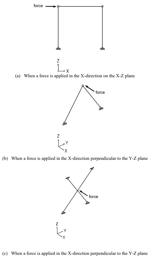
As shown in Figure 1, you should exercise caution not to induce unstable structures when only truss elements are connected. The structure shown in Figure 1 (a) lacks rotational stiffness while being subjected to an external load in its plane, resulting in an unstable condition. Figures 1 (b) and (c) illustrate unstable structures in the loading direction (X-Z plane), even though the structures are stable in the Y-Z plane direction.
You should use tension-only and compression-only elements with care. Element stiffness may be ignored in the analysis depending on the magnitudes of loads; e.g., when compression loads are applied to tension-only elements.
Beam Element
This element is typically used for modeling prismatic and non-prismatic tapered structural members that are relatively long compared to section dimensions. The element can be also used as load-transfer elements connecting other elements having differing numbers of d.o.f.
In-span concentrated loads, distributed loads, temperature gradient loads and prestress loads can be applied to beam elements.
A beam element has 6 d.o.f. per node reflecting axial, shear, bending and torsional stiffness. When shear areas are omitted, the corresponding shear deformations of the beam element are ignored.
The beam element is formulated on the basis of the Timoshenko beam theory (a plane section initially normal to the neutral axis of the beam remains plane but not necessarily normal to the neutral axis in the deformed state) reflecting shear deformations. If the ratio of the section depth to length is greater than 1/5, a fine mesh modeling is desirable because the effect of shear deformations becomes significant.
The torsional resistance of a beam element differs from the sectional polar moment of inertia (they are the same for circular and cylindrical sections). You are cautioned when the effect of torsional deformation is large, as the torsional resistance is generally determined by experimental methods.
* Refer to Numerical Analysis Model in MIDAS/Gen>Stiffness Data of Elements.
Beam and truss elements are idealized line elements, thus their cross-sections are assumed to be dimensionless. The cross-sectional properties of an element are concentrated at the neutral axis that connects the end nodes. As a result, the effects of panel zones between members (regions where columns and beams merge) and the effects of non-alignment of neutral axes are not considered. In order for those nodal effects to be considered, the beam end offset option or geometric constraints must be used.
* Refer to Numerical Analysis Model in MIDAS/Gen > Other Modeling Functions > Beam End Offset.
The tapered section may be used when the section of a member is non-prismatic. It may be desirable to use a number of beam elements to model a curved beam.
* Refer to “Model > Properties > Section” of On-line Manual.
When members are connected by pins or slotted holes (Figure 2 (a) and (b)), the Beam End Release option is used.
* Refer to “Model > Boundaries > Beam End Release” of On-line Manual.
Note that a singularity error can result in a case where a particular degree of freedom is released for all the elements joining at a node, resulting in zero stiffness associated with that degree of freedom. If it is inevitable, a spring element (or an elastic boundary element) having a minor stiffness must be added to the corresponding d.o.f.
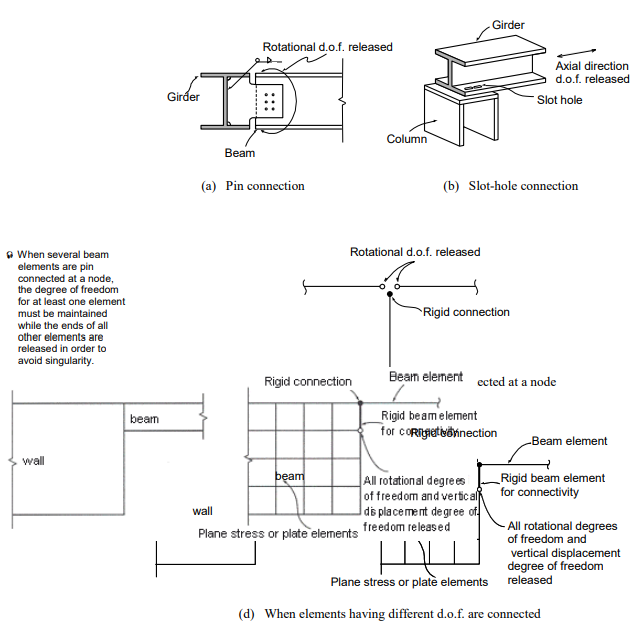
The rigid beam element can be effectively used when elements having different degrees of freedom are connected. The rigid effect is achieved by assigning a large stiffness value relative to the contiguous beam elements. In general, a magnitude of 105 ~ 108 times the stiffness of the neighboring elements provides an adequate result, avoiding numerical ill conditions.
Figure 2 (d) illustrates the case where a beam member is joined to a wall. The wall element may be plane stress or plate element. The nodal in-plane moment corresponding to the beam element’s rotational degree of freedom will not be transmitted to the planar element (plane stress or plate element) because the planar element has no rotational stiffness about the normal direction to the plane. The interface will behave as if the beam was pin connected. In such a case, a rigid beam element is often introduced in order to maintain compatible connectivity. All degrees of freedom of the rigid beam at the beam element is fully maintained while the rotational and axial displacement degrees of freedom are released at the opposite end.
Plane Stress Element
This element can be used for modeling membrane structures that are subjected to tension or compression forces in the plane direction only. Pressure loads can be applied normally to the perimeter edges of the plane stress element.
The plane stress element may retain a quadrilateral or triangular shape. The element has in-plane tension, compression and shear stiffness only.
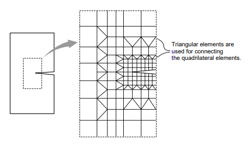
Quadrilateral (4-node) elements, by nature, generally lead to accurate results for the computation of both displacements and stresses. On the contrary, triangular elements produce poor results in stresses, although they produce relatively accurate displacements. Accordingly, you are encouraged to avoid triangular elements at the regions where detailed analysis results are required, and they are recommended for the transition of elements only (Figure 3).
Singularity errors occur during the analysis process, where a plane stress element is joined to elements with no rotational degrees of freedom since the plane stress element does not have rotational stiffness. In MIDAS/Gen, restraining the rotational degrees of freedom at the corresponding nodes prevents singularity errors.
When a plane stress element is connected to elements having rotational stiffness such as beam and plate elements, the connectivity between elements needs to be preserved using the rigid link (master node and slave node) option or the rigid beam element option.
Appropriate aspect ratios for elements may depend on the type of elements, the geometric configuration of elements, and the shape of the structure. However, aspect ratios close to unity (1:1) and 4 corner angles close to 90° are recommended. If the use of regular element sizes cannot be achieved throughout the structure, the elements should be square-shaped at least at the regions where stress intensities are expected to vary substantially and where detailed results are required.
Relatively small elements result in better convergence.
Plane Strain Element
This element can be used to model a long structure, having a uniform cross-section along its entire length, such as dams and tunnels. The element cannot be used in conjunction with any other types of elements.
Pressure loads can be applied normally to the perimeter edges of the plane strain element.
Because this element is formulated on the basis of its plane strain properties, it is applicable to linear static analyses only. Given that no strain is assumed to exist in the thickness direction, the stress component in the thickness direction can be obtained through the Poisson’s effect.
The plane strain element may retain a quadrilateral or triangular shape. The element has in-plane tension, compression, and shear stiffness, and it has tension and compression stiffness in the thickness direction.
Similar to the plane stress element, quadrilateral elements are recommended over the triangular elements, and aspect ratios close to unity are recommended for modeling plane strain elements.
* Refer to “Plane Stress Element”.
Axisymmetric Element
This element can be used for modeling a structure with axis symmetry relative to the geometry, material properties, and loading conditions, such as pipes, vessels, tanks, and bins. The element cannot be used in conjunction with any other types of elements.
Pressure loads can be applied normally to the circumferential edges of the axisymmetric element.
Because this element is formulated on the basis of its axisymmetric properties, it is applicable to linear static analyses only. It is assumed that circumferential displacements, shear strains, and shear stresses do not exist.
Similar to the plane stress element, quadrilateral elements are recommended over the triangular elements, and aspect ratios close to unity are recommended for modeling axisymmetric elements.
* Refer to “Plane Stress Element”.
Plate Element
This element can be used to model the structures in which both in-plane and out-of-plane
bending deformations are permitted to take place, such as pressure vessels, retaining walls, bridge decks, building floors and mat foundations.
Pressure loads can be applied to the surfaces of the elements in either the GCS or ECS.
A plate element can be either quadrilateral or triangular in shape where its stiffness is formulated in two directions, in-plane direction axial and shear stiffness and out-of-plane bending and shear stiffness.
The out-of-plane stiffness used in MIDAS/Gen includes two types of elements, DKT/DKQ (Discrete Kirchhoff elements) and DKMT/DKMQ (Discrete Kirchhoff-Mindlin elements). DKT/DKQ were developed on the basis of the Kirchhoff Thin Plate theory. Whereas, DKMT/DKMQ were developed on the basis of the Mindlin-Reissner Thick Plate theory, which results in superb performances on thick plates as well as thin plates by incorporating appropriate shear strain fields to resolve the shear-locking problem. The in-plane stiffness of the triangular element is formulated in accordance with the Linear Strain Triangle (LST) theory, whereas the Isoparametric Plane Stress Formulation with Incompatible Modes is used for the quadrilateral element.
The user may separately enter different thicknesses for an element for calculating the in-plane stiffness and the out-of-plane stiffness. In general, the self-weight and mass of an element are calculated from the thickness specified for the in-plane stiffness. However, if only the thickness for the out-of-plane stiffness is specified, they are calculated on the basis of the thickness specified for the out-of-plane stiffness.
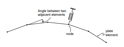
Similar to the plane stress element, the quadrilateral element type is recommended for modeling structures with plate elements. When modeling a curved plate, the angles between two adjacent elements should remain at less than 10°. Moreover, the angles should not exceed 2~3° in the regions where precise results are required.
It is thus recommended that elements close to squares be used in the regions where stress intensities are expected to vary substantially and where detailed results are required.
Solid Element
This element is used for modeling three-dimensional structures, and its types include tetrahedron, wedge, and hexahedron.
Pressure loads can be applied normally to the surfaces of the elements or in the X, Y, and Z-axes of the GCS.
The use of hexahedral (8-node) elements produces accurate results in both displacements and stresses. On the other hand, using the wedge (6-node) and tetrahedron (4-node) elements may produce relatively reliable results for displacements, but poor results are derived from stress calculations. It is thus recommended that the use of the 6-node and 4-node elements be avoided if precise analysis results are required. The wedge and tetrahedron elements, however, are useful to join hexahedral elements where element sizes change.
Solid elements do not have a stiffness to rotational d.o.f. at adjoining nodes. Joining elements with no rotational stiffness will result in singular errors at their nodes. In such a case, MIDAS/Gen automatically restrains the rotational d.o.f. to prevent singular errors at the corresponding nodes.
When solid elements are connected to other elements retaining rotational stiffness, such as beam and plate elements, introducing rigid links (master node and slave node feature in MIDAS/Gen) or rigid beam elements can preserve the compatibility between two elements.
An appropriate aspect ratio of an element may depend on several factors such as the element type, geometric configuration, structural shape, etc. In general, it is recommended that the aspect ratio be maintained close to 1.0. In the case of a hexahedral element, the corner angles should remain at close to 90°. It is particularly important to satisfy the configuration conditions where accurate analysis results are required or significant stress changes are anticipated. It is also noted that smaller elements converge much faster.
Fill out the form below in order to download the full content!