 Banner Title Products
OVERVIEW
In small and medium-sized frame structures, very thin members such as angles and rod-bars are used for diagonal members or wind braces installed for structural stability or safety during construction. However, designing these slender members to resist compressive forces is very difficult and uneconomical. Therefore, as a way to solve this problem, when performing structural analysis, a method of performing a non-linear analysis that uses a tension-only element to limit the stiffness in the analysis is applied so that the elongated member does not resist the compressive force.
For nonlinear elements such as tension-only, compression-only, and cable, the load acting on the element or the stiffness matrix of the structure changes due to the displacement and member force generated according to the load during the iterative analysis process. Therefore, general load combination conditions that linearly combine analysis results for each unit load cannot be used.
In this case, the correct member force of nonlinear elements can be obtained only when the load combination conditions to be considered in the design are applied as unit load condition for each analysis.
However, it is very difficult and cumbersome for the user to input the load every time to match the numerous load combination conditions. In this case, by using the 'Create Load Cases Using Load Combinations' function provided by midas Gen, the load to be considered in the load combination condition to be applied to the design can be easily entered as each unit load condition.
This document briefly introduces the functions related to ‘Create Load Cases Using Load Combinations’ when some nonlinear elements are used in the structure, and explains the modeling and analysis process according to the procedure. In addition, the member force of non-linear elements by non-linear analysis was compared when the analysis results of the unit load condition were linearly combined and when the load combination condition was converted into a unit load condition.
The structure of the main text is divided into two parts.
(1) Modeling and Analysis Considerations for Tension-Only Element Analysis
∙ ‘Create Load Cases Using Load Combinations’ function
∙ Selection of convergence method when analyzing non-linear elements of Model Control Data
∙ Check the convergence error condition in the Analysis Message window
(2) Tension-only element modeling, structural analysis and design procedure using midas Gen
Modeling and Analysis Considerations for Tension-Only Element Analysis
‘Create Load Cases Using Load Combinations’ Function
midas Gen supports the automatic conversion of a load combination including various load cases into a single static load case with a load factor applied.
The list of load combinations defined in the model is displayed, and the list of load combinations to be created as a unit load condition for nonlinear analysis is sent to the Selected Combinations list. The load condition created here can also be reflected as a load combination for use in design.
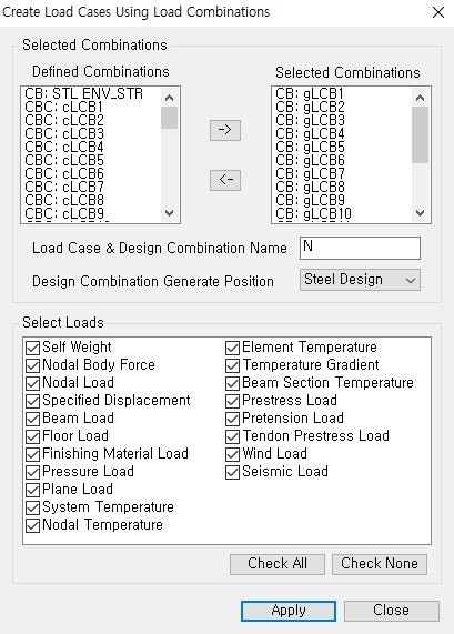 Figure 1. Create Load Cases Using Load Combinations Dialog Box
The Select Loads function automatically selects the type of load to be considered as a new unit load condition from among the loads reflected in the existing load combination conditions. If you click [Apply], all loads entered in the unit load conditions (DL, LL) constituting the load combination condition (CB: gLCB1) are reflected up to each load factor, and a new unit load condition (NgLCB1) is automatically created.
For reference, the tensile element can be applied to static analysis, nonlinear analysis (large deformation analysis), construction stage analysis, and PSC analysis. In other analyzes, truss elements are not replaced or nonlinear analysis is not performed. In particular, when performing seismic analysis, in eigenvalue analysis and response spectrum analysis, the tensile element is replaced by the truss element and compressive force may occur in the member, so please be careful when performing the analysis.
Selection of Convergence Method When Analyzing Non-Linear Elements of Model Control Data
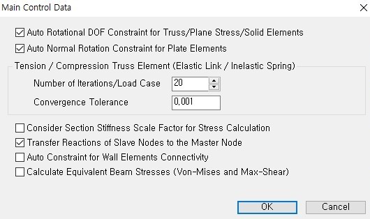
Before performing structural analysis, specify the convergence condition for nonlinear analysis in Analysis > Model Control Data.
‘Number of Iterations/Load Case’ indicates the maximum number of iterations and ‘Convergence Tolerance’ means the limit of convergence error.
Convergence Error Condition in the Analysis Message Window
The analysis is performed according to the condition reached among two cases: the maximum number of iterations and the convergence error limit. Therefore, after the analysis is terminated, it is necessary to check whether the convergence condition specified in the analysis message window is satisfied. If the analysis is terminated due to the limitation of the number of iterations even though it has not converge, the reanalysis is performed by increasing the maximum number of iterations.
The maximum number of iterations of the example is ‘20’, and the convergence error is ‘0.001’. Figure 3 shows the analysis message displayed on the analysis message window when performing nonlinear analysis.
If you look at the message, it can be seen that the stiffness is reconstructed for each of the 24 existing load cases, and in the case of the 24th load case, the analysis is finished by satisfying the limit of convergence error in the 4th analysis without convergence until the 3rd analysis. Here, 'Displacement Error Norm' indicates the degree of convergence of the analysis value based on the displacement during repeated analysis ({un } − {un−1}/{un }), and the convergence error specified by the user in Analysis > Main Control Data. If it is smaller than 'Convergence Tolerance', which is the limit of, it is judged that the analysis result converges.
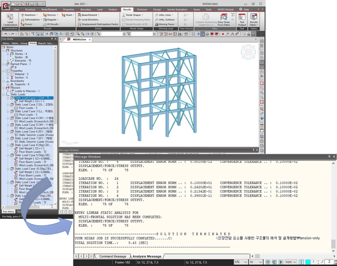 Figure 3. Nonlinear Analysis and Analysis Message
Nonlinear Element Modeling, Structural Analysis and Design Procedure Using midas Gen
In midas Gen, using the Load > Create Load Cases Using Load Combinations function, the design load combination condition can be easily replaced with a unit load condition, and all loads of the design load combination condition can be automatically entered as the unit load condition.
Here's how to apply many of the above-mentioned considerations to real-world models.
This model is based on the attached simple model.
(1) In File > Open Project, import the attached model tension-only (modeling).mgb.
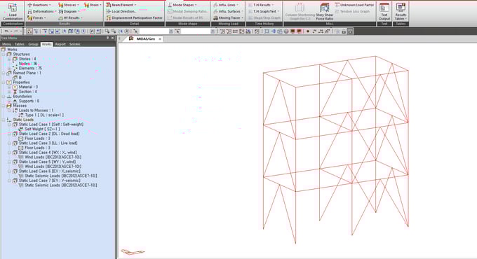 Figure 4. Example Model
(2) In Result > Combinations, create load combination conditions using the [Auto Generation] button.
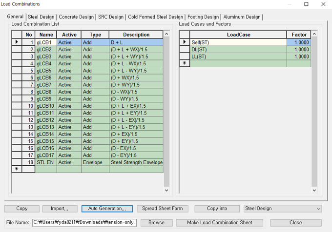 Figure 5. Create Load Combination Condition
If you would like to read full contents, please download White Paper VOL.17 Design Method of Structures Using Cable and Truss Elements below.