 Banner Title Products
OVERVIEW
The MIDAS/Gen element library consists of the following elements:
▶ Tension-only Element (Hook and Cable function included)
▶ Compression-only Element (Gap function included)
▶ Beam Element/Tapered Beam Element
▶ Two-dimensional Plane Strain Element
▶ Two-dimensional Axisymmetric Element
Defining the types of elements, element material properties and element stiffness data completes data entry for finite elements. Connecting node numbers are then specified to define the locations, shapes and sizes of elements.
Truss Element
A truss element is a two-node, uniaxial tension-compression three-dimensional line element. The element is generally used to model space trusses or diagonal braces. The element undergoes axial deformation only.
Element d.o.f. and ECS
All element forces and stresses are expressed with respect to the ECS. Especially, the ECS is consistently used to specify the shear and flexural stiffness of beam elements.
Only the ECS x-axis is structurally significant for the elements retaining axial stiffness only, such as truss elements and tension-only/compression-only elements. The ECS y and z-axes, however, are required to orient truss members’ cross-sections displayed graphically.
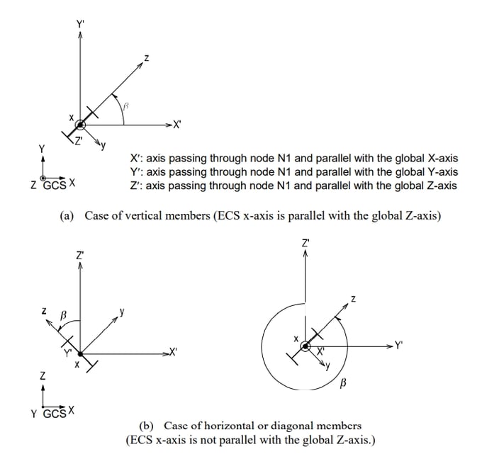
MIDAS/Gen uses the Beta Angle (β) conventions to identify the orientation of each cross-section. The Beta Angle relates the ECS to the GCS. The ECS x-axis starts from node N1 and passes through node N2 for all line elements (Figures 1 and 2). The ECS z-axis is defined to be parallel with the direction of “H” dimension of cross-sections. That is, the y-axis is in the strong axis direction. The use of the right-hand rule prevails in the process.
If the ECS x-axis for a line element is parallel with the GCS Z-axis, the Beta angle is defined as the angle formed from the GCS X-axis to the ECS z-axis. The ECS x-axis becomes the axis of rotation for determining the angle using the right-hand rule. If the ECS x-axis is not parallel with the GCS Z-axis, the Beta angle is defined as the right angle to the ECS x-z plane from the GCS Z-axis.
Functions related to the elements
Create Elements
Material: Material properties
Section: Cross-sectional properties
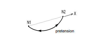
Pretension Loads
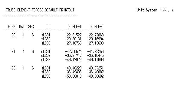
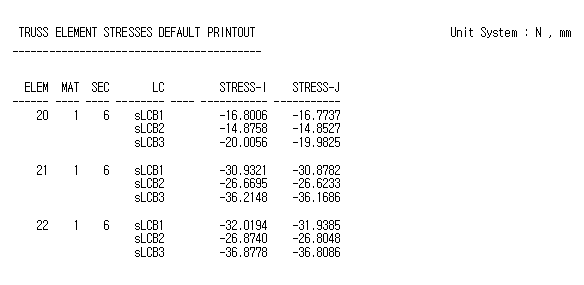
Output for element forces
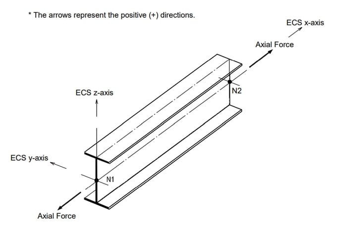
The sign convention for truss element forces is shown in Figure 2. The arrows represent the positive (+) directions.
Tension-Only Element
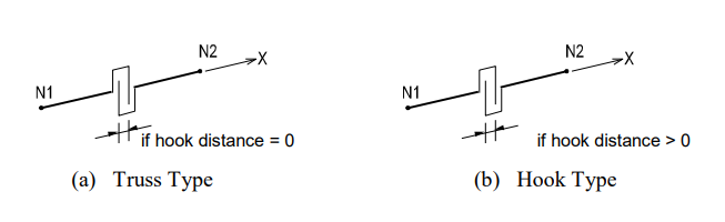
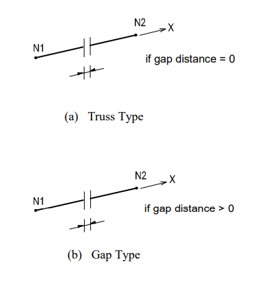
Two nodes define a tension-only, three-dimensional line element. The element is generally used to model wind braces and hook elements. This element undergoes axial tension deformation only. The tension-only elements include the following types:
Truss: A truss element transmits axial tension forces only.
Hook: A hook element retains a specified initial hook distance. The element stiffness is engaged after the tension deformation exceeds that distance.
* Refer to “Analysis > Main Control Data” of On-line Manual.
Element d.o.f. and the ECS
The element d.o.f. and the ECS of a tension-only element are identical to that of a truss element.
Functions related to elements
Main Control Data: Convergence conditions are identified for Iterative Analysis using tension-only elements.
Material: Material properties
Section: Cross-sectional properties
Pretension Loads
* A nonlinear structural analysis reflects the change in stiffness due to varying member forces. The iterative analysis means to carry out the analysis repeatedly until the analysis results satisfy the given convergence conditions.
Output for element forces
Tension-only elements use the same sign convention as truss elements.
Cable Element
Two nodes define a tension-only, three-dimensional line element, which is capable of transmitting axial tension force only. A cable element reflects the change in stiffness varying with internal tension forces.
A cable element is automatically transformed into an equivalent truss element and an elastic catenary cable element in the cases of linear analysis and a geometric nonlinear analysis respectively.
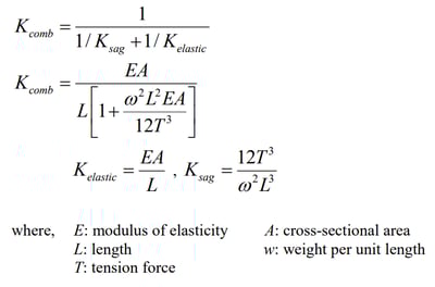
Equivalent truss element
The stiffness of an equivalent truss element is composed of the usual elastic stiffness and the stiffness resulting from the sag, which depends on the magnitude of the tension force. The following expressions calculate the stiffness:
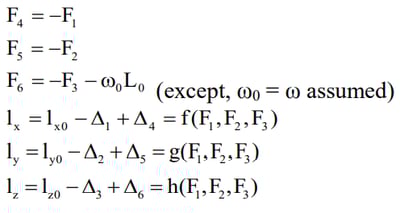
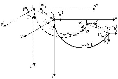
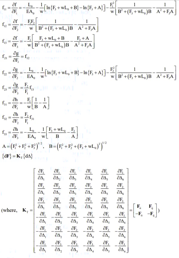
The tangent stiffness of a cable element applied to a geometric nonlinear analysis is calculated as follows:
Figure 7. illustrates a cable connected by two nodes where displacements Δ1, Δ2 & Δ3 occur at Node i and Δ4, Δ5 & Δ6 occur at Node j, and as a result, the nodal forces F01, F02, F03, F04, F05, F06 are transformed into F1, F2, F3, F4, F5, F6 respectively. Then, the equilibriums of the nodal forces and displacements are expressed as follows: Figure 7. illustrates a cable connected by two nodes where displacements Δ1, Δ2 & Δ3 occur at Node i and Δ4, Δ5 & Δ6 occur at Node j, and as a result, the nodal forces F01, F02, F03, F04, F05, F06 are transformed into F1, F2, F3, F4, F5, F6 respectively. Then, the equilibriums of the nodal forces and displacements are expressed as follows:
The differential equations for each directional length of the cable in the Global Coordinate System are noted below. When we rearrange the load-displacement relations we can then obtain the flexibility matrix, ([F]). The tangent stiffness, ([K]), of the cable can be obtained by inverting the flexibility matrix. The stiffness of the cable cannot be obtained immediately rather repeated analyses are carried out until it reaches an equilibrium state.
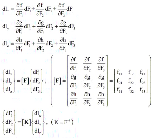
The components of the flexibility matrix are expressed in the following equations:
Compression-Only Element
Two nodes define a compression-only, three-dimensional line element. The element is generally used to model contact conditions and support boundary conditions. The element undergoes axial compression deformation only.
The compression-only elements include the following types:
Truss: A truss element transmits axial compression forces only.
Gap: A gap element retains a specified initial gap distance. The element stiffness is engaged after the compression deformation exceeds that distance.
Element d.o.f. and the ECS
The element d.o.f. and the ECS of a compression-only element are identical to that of a truss element.
* See “Analysis> Main Control Data” of On-line Manual.
Functions related to the elements
Main Control Data: Convergence conditions are identified for Iterative Analysis using tension/compression-only elements.
Material: Material properties
Section: Cross-sectional properties
Pretension Loads
Output for element forces
Compression-only elements use the same sign convention as truss elements.
Beam Element
Two nodes define a Prismatic/Non-prismatic, three-dimensional beam element. Its formulation is founded on the Timoshenko Beam theory taking into account the stiffness effects of tension/compression, shear, bending and torsional deformations. In the Section Dialog Box, only one section is defined for a prismatic beam element whereas, two sections corresponding to each end are required for a non-prismatic beam element. MIDAS/Gen assumes linear variations for cross-sectional areas, effective shear areas and torsional stiffness along the length of a non-prismatic element. For moments of inertia about the major and minor axes, you may select a linear, parabolic or cubic variation.
Element d.o.f. and the ECS
Each node retains three translational and three rotational d.o.f. irrespective of the ECS or GCS. The ECS for the element is identical to that for a truss element.
Functions related to the elements
Create Elements
Material: Material properties
Section: Cross-sectional properties
Beam End Release: Boundary conditions at each end (end-release, fixed or hinged)
Beam End Offsets: Rigid end offset distance
Element Beam Loads: Beam loads (In-span concentrated loads or distributed loads)
Line Beam Loads: Beam loads within a specified range
Assign Floor Load: Floor loads converted into beam loads
Prestress Beam Load: Prestress or post-tension loads
Temperature Gradient
Output for element forces
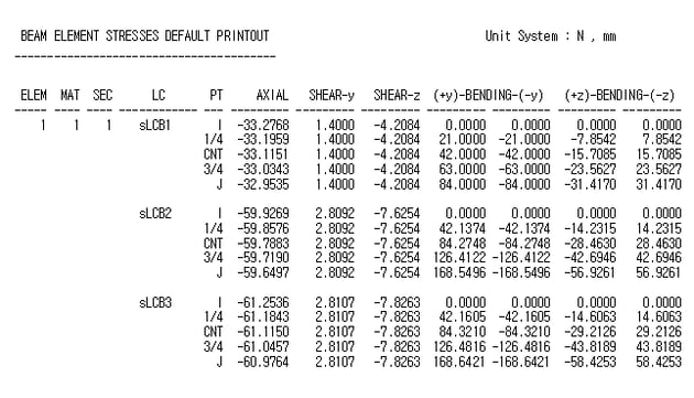
The sign convention for beam element forces is shown in Figure 9. The arrows represent the positive (+) directions. Element stresses follow the same sign convention. However, stresses due to bending moments are denoted by ‘+’ for tension and ‘-’ for compression.
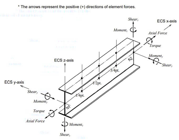
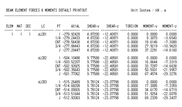
Figure 10. Sample Output of Beam Element Forces
Plane Stress Element
Three or four nodes placed in the same plane define a plane stress element. The element is generally used to model membranes that have a uniform thickness over the plane of each element. Loads can be applied only in the direction of its own plane.
This element is formulated according to the Isoparametric Plane Stress Formulation with Incompatible Modes. Thus, it is premised that no stress components exist in the out-of-plane directions and that the strains in the out-of-plane directions can be obtained on the basis of the Poisson’s effects.
Element d.o.f. and the ECS
The element retains displacement d.o.f. in the ECS x and y-directions only.
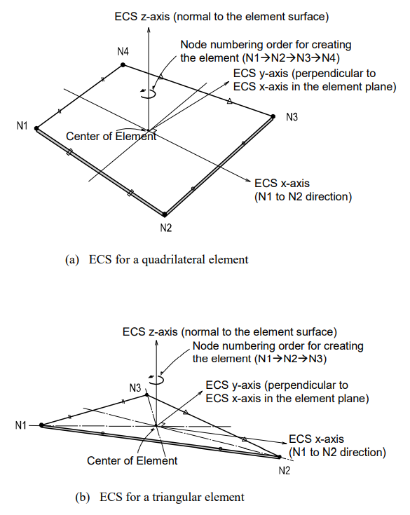
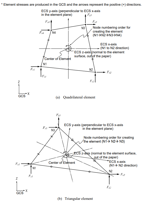
The ECS uses x, y & z-axes in the Cartesian coordinate system, following the right-hand rule. The directions of the ECS axes are defined as presented in Figure 12.
In the case of a quadrilateral (4-node) element, the thumb direction signifies the ECS z-axis. The rotational direction (N1>N2>N3>N4) following the right-hand rule determines the thumb direction. The ECS z-axis originates from the center of the element surface and is perpendicular to the element surface. The line connecting the midpoint of N1 and N4 to the midpoint of N2 and N3 defines the direction of ECS x-axis. The perpendicular direction to the x-axis in the element plane now becomes the ECS y-axis by the right-hand rule.
For a triangular (3-node) element, the line parallel to the direction from N1 to N2, originating from the center of the element becomes the ECS x-axis. The y and z-axes are identically defined as those for the quadrilateral element.
Functions related to the elements
Create Elements
Material: Material properties
Thickness: Thickness of the element
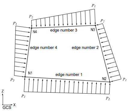
Pressure Loads: Pressure loads acting normal to the edges of the element
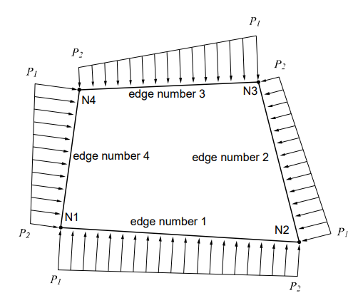
Figure 13 illustrates pressure loads applied normal to the edges of a plane stress element.
Output for element forces
The sign convention for element forces and element stresses is defined relative to either the ECS or GCS. The following descriptions are based on the ECS:
- Output for element forces at connecting nodes
- Output for element stresses at connecting nodes and element centers
At a connecting node, multiplying each nodal displacement component by the corresponding stiffness component of the element produces the element forces.
For stresses at the connecting nodes and element centers, the stresses calculated at the integration points (Gauss Points) are extrapolated.
- Output for element forces
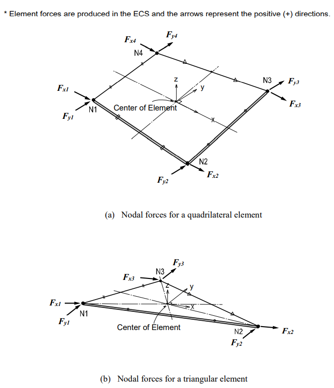
Figure 14 shows the sign convention for element forces. The arrows represent the positive (+) directions.
- Output for element Stresses
Figure 15 shows the sign convention for element stresses. The arrows represent the positive (+) directions.
Two-Dimensional Plane Strain Element
2-D Plane Strain Element is a suitable element type to model lengthy structures of uniform cross-sections such as dams and tunnels. The element is formulated on the basis of Isoparametric Plane Strain Formulation with Incompatible Modes.
The element cannot be combined with other types of elements. It is only applicable for linear static analyses due to the characteristics of the element.
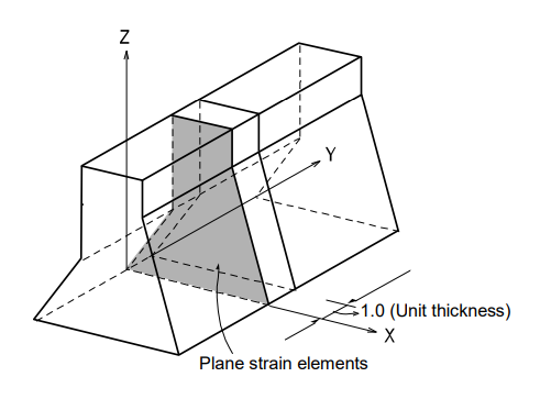
Elements are entered in the X-Z plane and their thickness is automatically given a unit thickness as shown in Figure 18.
Because the formulation of the element is based on its plane strain properties, it is premised that strains in the out-of-plane directions do not exist. Stress components in the out-of-plane directions can be obtained only based on the Poisson’s Effects.
Element d.o.f. and the ECS
The ECS for plane strain elements is used when the program calculates the element stiffness matrices. Graphic displays for stress components are also depicted in the ECS in the post-processing mode.
The element d.o.f. exists only in the GCS X and Z-directions.
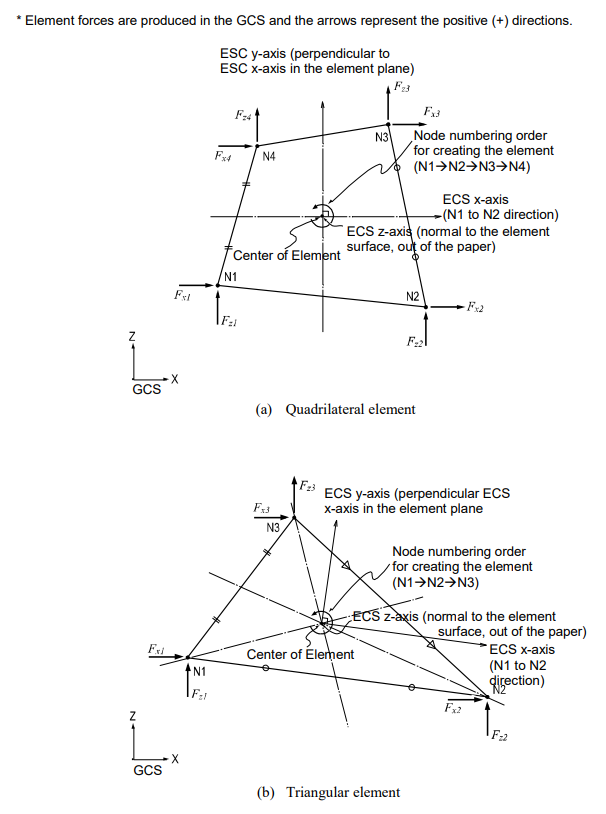
The ECS uses x, y & z-axes in the Cartesian coordinate system, following the right-hand rule. The directions of the ECS axes are defined as presented in Figure 19.
In the case of a quadrilateral (4-node) element, the thumb direction signifies the ECS z-axis. The rotational direction (N1>N2>N3>N4) following the right-hand rule determines the thumb direction. The ECS z-axis originates from the center of the element surface and is perpendicular to the element surface. The line connecting the midpoint of N1 and N4 to the midpoint of N2 and N3 defines the direction of ECS x-axis. The perpendicular direction to the x-axis in the element plane now becomes the ECS y-axis by the right-hand rule.
For a triangular (3-node) element, the line parallel to the direction from N1 to N2, originating from the center of the element becomes the ECS x-axis. The y and z-axes are identically defined as those for the quadrilateral element.
Functions related to the elements
Create Elements
Material: Material properties
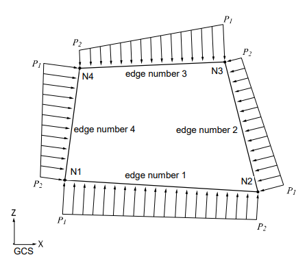
Pressure Loads: Pressure loads acting normal to the edges of the element
Figure 20. illustrates pressure loads applied normally to the edges of a plane strain element. The pressure loads are automatically applied to the unit thickness defined in Figure 18.
Output for Element Forces
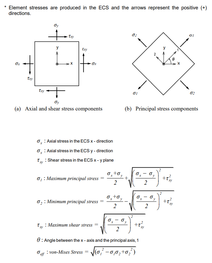
The sign convention for plane strain element forces and stresses is defined relative to either the ECS or GCS. Figure 21 illustrates the sign convention relative to the ECS or principal stress directions of a unit segment.
- Output for element forces at connecting nodes
- Output for element stresses at connecting nodes and element centers
At a connecting node, multiplying each nodal displacement component by the corresponding stiffness component of the element produces the element forces.
For stresses at the connecting nodes and element centers, the stresses calculated at the integration points (Gauss Points) are extrapolated.
- Output for element forces Figure 19 shows the sign convention for element forces. The arrows represent the positive (+) directions.
- Output for element stresses Figure 21 shows the sign convention for element stresses. The arrows represent the positive (+) directions.
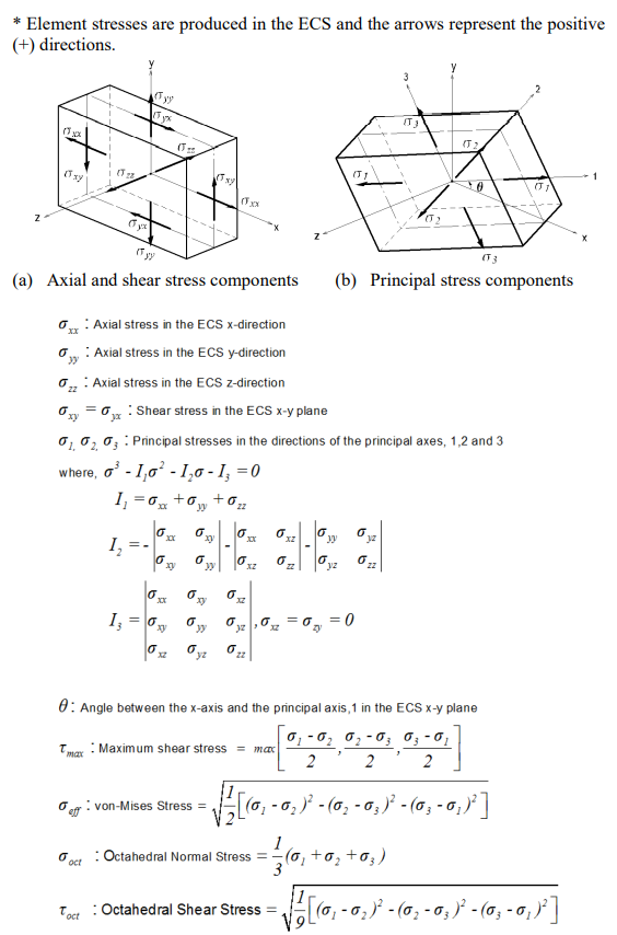
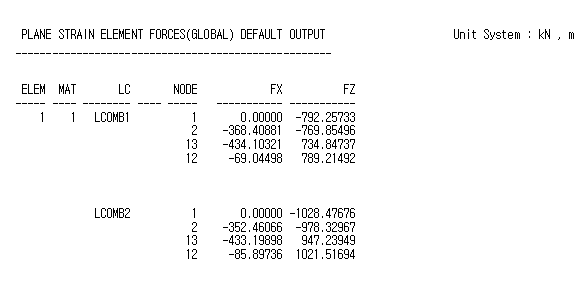
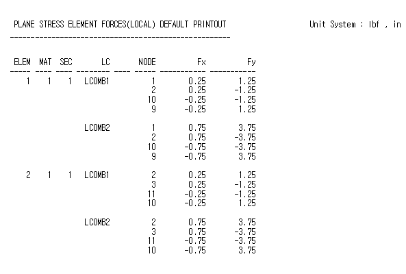
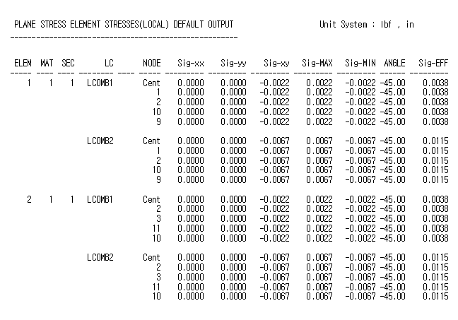
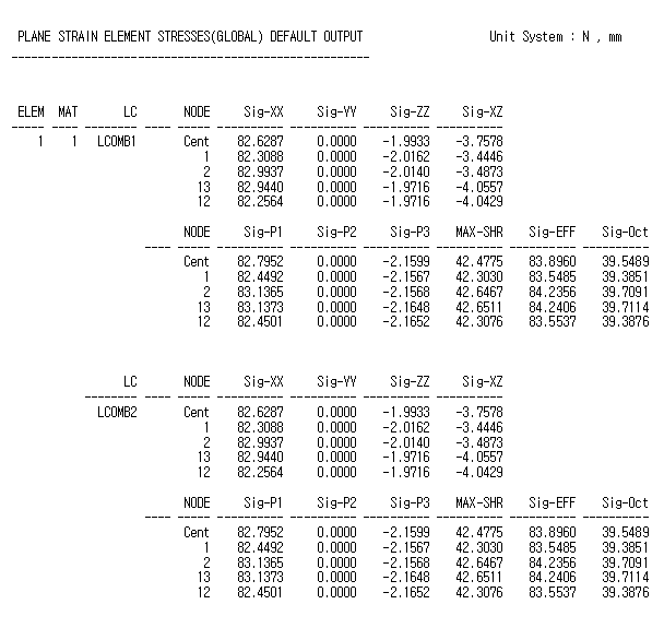
Figure 22. Sample Output of Plane Strain Element Forces
Two-Dimensional Axisymmetric Element
Two-Dimensional Axisymmetric Elements are suitable for modeling structures with a radial symmetry relative to geometries, material properties and loading conditions. Application examples may be pipes and cylindrical vessel bodies including heads. The elements are developed on the basis of the isoparametric formulation theory. The element cannot be combined with other types of elements. It is only applicable for linear static analyses due to the characteristics of the element.
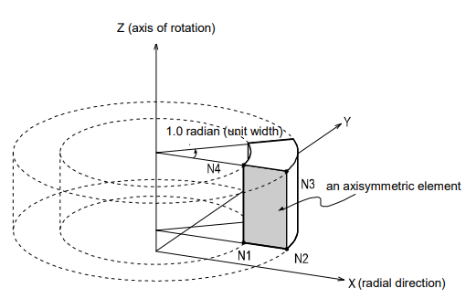
2-D axisymmetric elements are derived from 3-D axisymmetric elements by taking the radial symmetry into account. The GCS Z-axis is the axis of rotation. The elements must be located in the global X-Z plane to the right of the global Z-axis. In this case, the radial direction coincides with the GCS X-axis. The elements are modeled such that all the nodes retain positive X-coordinates (X≥0).
By default, the thickness of the element is automatically preset to a unit thickness (1.0 radian) as illustrated in Figure 24.
Because the formulation of the element is based on the axisymmetric properties, it is premised that circumferential displacements, shear strains (gXY, gYZ) and shear stresses (tXY, tYZ) do not exist.
Element d.o.f. and the ECS
The ECS for axisymmetric elements is used when the program calculates the element stiffness matrices. Graphic displays for stress components are also depicted in the ECS in the post-processing mode.
The element d.o.f. exists only in the GCS X and Z-directions.
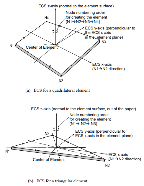
The ECS uses x, y & z-axes in the Cartesian coordinate system, following the right-hand rule. The directions of the ECS axes are defined as presented in Figure 25.
In the case of a quadrilateral (4-node) element, the thumb direction signifies the ECS z-axis. The rotational direction (N1>N2>N3>N4) following the right-hand rule determines the thumb direction. The ECS z-axis originates from the center of the element surface and is perpendicular to the element surface. The line connecting the midpoint of N1 and N4 to the midpoint of N2 and N3 defines the direction of ECS x-axis. The perpendicular direction to the x-axis in the element plane now becomes the ECS y-axis by the right-hand rule.
For a triangular (3-node) element, the line parallel to the direction from N1 to N2, originating from the center of the element becomes the ECS x-axis. The y and z-axes are identically defined as those for the quadrilateral element.
Functions related to the elements
Create Elements
Material: Material properties
Pressure Loads: Pressure loads acting normal to the edges of the element
Figure 26 illustrates pressure loads applied normal to the edges of an axisymmetric element. The pressure loads are automatically applied to the width of 1.0 Radian as defined in Figure 24.
Output for Element Forces
The sign convention for axisymmetric element forces and stresses is defined relative to either the ECS or GCS. Figure 27 illustrates the sign convention relative to the ECS or principal stress directions of a unit segment.
- Output for element forces at connecting nodes
- Output for element stresses at connecting nodes and element centers
At a connecting node, multiplying each nodal displacement component by the corresponding stiffness component of the element produces the element forces.
For stresses at the connecting nodes and element centers, the stresses calculated at the integration points (Gauss Points) are extrapolated.
- Output for element forces Figure 25 shows the sign convention for element forces. The arrows represent the positive (+) directions.
- Output for element stresses Figure 27 shows the sign convention for element stresses. The arrows represent the positive (+) directions.
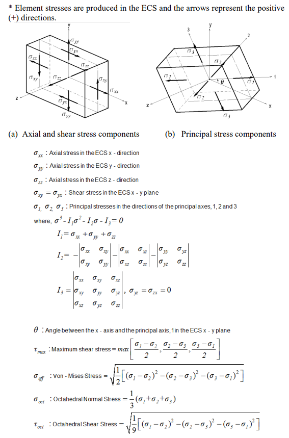
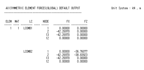
Figure 28. Sample Output of Axisymmetric Element Forces
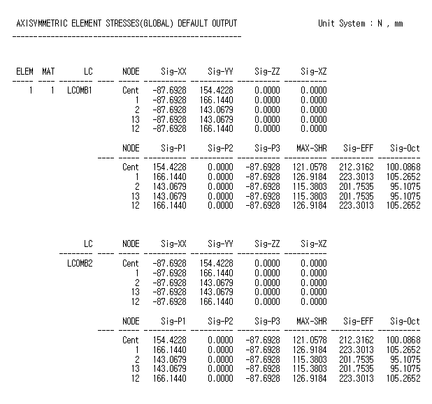
Plate Element
Three or four nodes placed in the same plane define a plate element. The element is capable of accounting for in-plane tension/compression, in-plane/out-of-plane shear and out-of-plane bending behaviors.
The out-of-plane stiffness used in MIDAS/Gen includes two types, DKT/DKQ (Discrete Kirchhoff element) and DKMT/DKMQ (Discrete Kirchhoff-Mindlin element). DKT and DKQ are developed on the basis of a thin plate theory, Kirchhoff Plate theory. Whereas, DKMT and DKMQ are developed on the basis of a thick plate theory, Mindlin-Reissner Plate theory, which exhibits superb performance for thick plates as well as thin plates by assuming appropriate shear strain fields to resolve the shear-locking problem.
The in-plane stiffness is formulated according to the Linear Strain Triangle theory for the triangular element, and Isoparametric Plane Stress Formulation with Incompatible Modes is used for the quadrilateral element.
You may selectively enter separate thicknesses for the calculation of in-plane stiffness and out-of-plane stiffness. In general, the thickness specified for the in-plane stiffness is used for calculating self-weight and mass. When it is not specified, the thickness for the out-of-plane stiffness will be used.
Element d.o.f. and the ECS
The ECS for plate elements is used when the program calculates the element stiffness matrices. Graphic displays for stress components are also depicted in the ECS in the post-processing mode.
The element’s translational d.o.f. exists in the ECS x, y, and z-directions, and rotational d.o.f. exists in the ECS x and y-axes.
The ECS uses x, y & z-axes in the Cartesian coordinate system, following the right-hand rule. The directions of the ECS axes are defined as presented in Figure 29.
In the case of a quadrilateral (4-node) element, the thumb direction signifies the ECS z-axis. The rotational direction (N1>N2>N3>N4) following the right-hand rule determines the thumb direction. The ECS z-axis originates from the center of the element surface and is perpendicular to the element surface. The line connecting the mi point of N1 and N4 to the midpoint of N2 and N3 defines the direction of ECS x-axis. The perpendicular direction to the x-axis in the element plane now becomes the ECS y-axis by the right-hand rule.
For a triangular (3-node) element, the line parallel to the direction from N1 to N2, originating from the center of the element becomes the ECS x-axis. The y and z-axes are identically defined as those for the quadrilateral element.
Functions related to the elements
Create Elements
Material: Material properties
Thickness: Thickness of the element
Pressure Loads: Pressure loads acting normal to the plane of the element
Temperature Gradient
Output for element forces
The sign convention for plate element forces and stresses is defined relative to either the ECS or GCS. The following descriptions are based on the ECS.
- Output for element forces at connecting nodes
- Output for element forces per unit length at connecting nodes and element centers
- Output for element stresses at top and bottom surfaces at connecting nodes and element centers
At a connecting node, multiplying each nodal displacement component by the corresponding stiffness component of the element produces the element forces. In order to calculate element forces per unit length at a connecting node or an element center, the stresses are separately calculated for in-plane and out-of-plane behaviors and integrated in the direction of the thickness. The element forces per unit length can be effectively applied to the design of concrete members. For stresses at the connecting nodes and element centers, the stresses calculated at the integration points (Gauss Points) are extrapolated.
- Output for element forces Figure 31 shows the sign convention for element forces. The arrows represent the positive (+) directions.
- Output for element forces per unit length Figure 32 shows the sign convention for element forces per unit length at connecting nodes and element centers. The arrows represent the positive (+) directions.
- Output for element stresses Figure 33 (a) shows the top and bottom surface locations where element stresses are produced at connecting nodes and element centers. Figure 33 (b) shows the sign convention for element stresses.
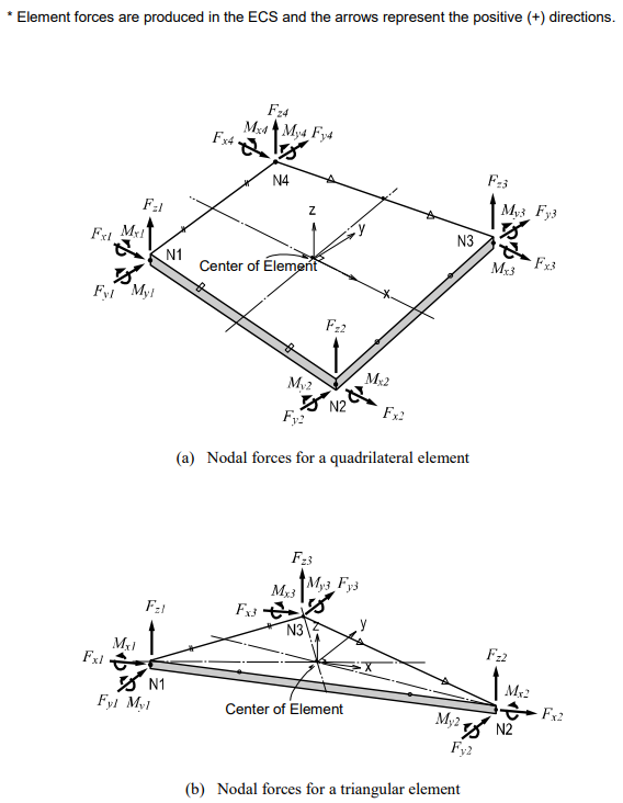
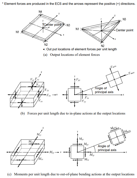 Figure 32. Output Locations of Plate Element Forces per Unit Length and the Sign Convention
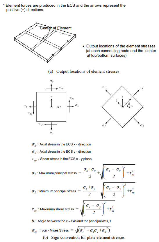
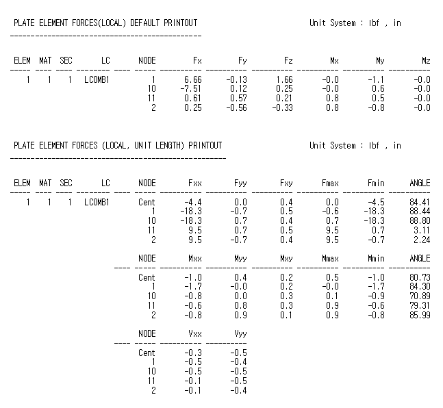 Figure 34. Sample Output of Plate Element Forces
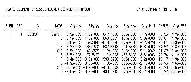
Solid Element
4, 6, or 8 nodes in a three-dimensional space define a solid element. The element is generally used to model solid structures or thick shells. A solid element may be a tetrahedron, wedge, or hexahedron. Each node retains three translational displacements d.o.f.
The element is formulated according to the Isoparametric Formulation with Incompatible Modes.
Element d.o.f., ECS and Element types
The ECS for solid elements is used when the program calculates the element stiffness matrices. Graphic displays for stress components are also depicted in the ECS in the post-processing mode.
The element d.o.f. exists in the translational directions of the GCS X, Y, and Z-axes.
The ECS uses x, y & z-axes in the Cartesian coordinate system, following the right-hand rule. The origin is located at the center of the element, and the directions of the ECS axes are identical to those of the plate element, plane number 1.
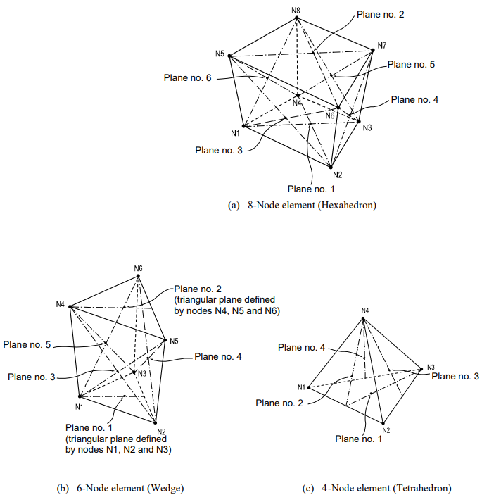
There are three types of elements, i.e., 8-node, 6-node, and 4-node elements, forming different shapes as presented in Figure 36. The nodes are sequentially numbered in an ascending order starting from N1 to the last number.
Functions related to the elements
Create Elements
Material: Material properties
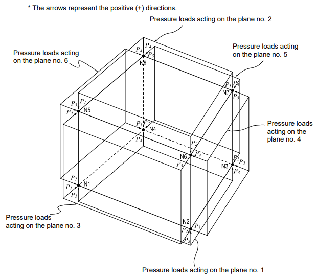
Pressure Loads: Pressure loads acting normal to the faces of the element
Loads are entered as pressure loads applied normally to each surface as illustrated in Figure 37.
Output for Element Forces
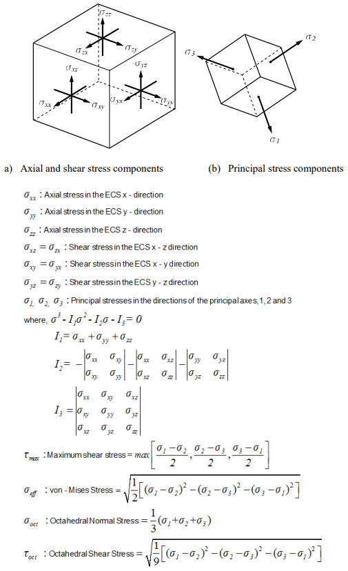
The sign convention for solid element forces and stresses is defined relative to either the ECS or GCS.
- Output for element forces at connecting nodes
- Output for three-dimensional element stress components at connecting nodes and element centers
At a connecting node, multiplying each nodal displacement component by the corresponding stiffness component of the element produces the element forces.
For stresses at the connecting nodes and element centers, the stresses calculated at the integration points (Gauss Points) are extrapolated.
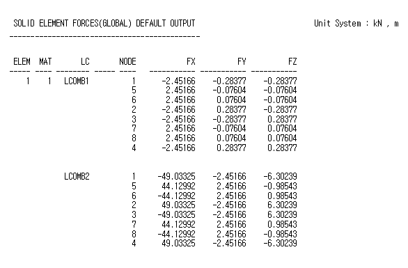
- Output for element forces
Figure 38 shows the sign convention for element forces. The arrows represent the positive (+) directions.
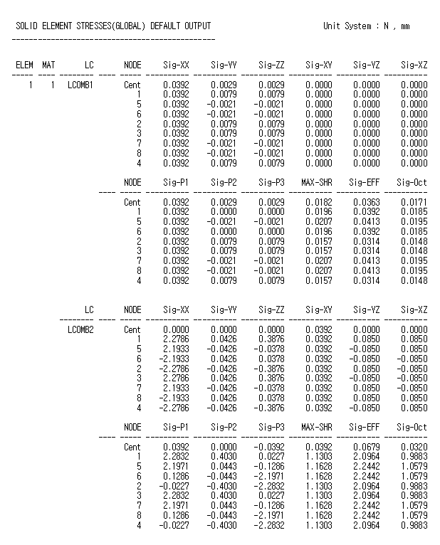
- Output for element stresses
Figure 39 shows the sign convention for element stresses. The arrows represent the positive (+) directions.
Wall Element
Wall elements are used to model shear walls, which retain the shape of a rectangle or square. The direction of gravity must be set opposite to the direction of the GCS Z-axis. The elements retain in-plane tension/compression stiffness in the vertical direction, in-plane shear stiffness in the horizontal direction, out-of-plane bending stiffness and rotational stiffness about the vertical direction.
Two types of wall elements included in MIDAS/Gen are:
-
Wall element type 1 (Membrane type):
in-plane stiffness + rotational stiffness about the vertical direction
-
Wall element type 2 (Plate type):
in-plane stiffness + rotational stiffness about the vertical direction + out-of-plane bending stiffness
Wall element type 1 (membrane type) is generally used to model shear walls being subjected to in-plane loads only. Whereas, Wall element type 2 (plate type) is suitable for modeling common walls intended to resist in-plane loads as well as out-of-plane bending moments.
Shear walls are generally modeled with 4-node plane stress elements, which best reflect the characteristics of shear walls. The plane stress elements included in most finite element programs, however, are not readily applicable for shear walls. This type of element does not have rotational stiffness about the axis perpendicular to the plane of the element at the connecting nodes. When flexural beams are connected to the wall element’s nodes, incompatibility in degrees of freedom results. Moreover, an additional transformation process is required for design because all element forces are produced in terms of nodal forces or stresses rather than wall member forces and moments.
In MIDAS/Gen, a new improved algorithm is used to overcome the limitation described above. This algorithm, if necessary, allows you to select out-of-plane bending stiffness to be included in the analysis.
The procedure for modeling wall elements in MIDAS/Gen is as follows:
- Enter the story data for the building.
- Enter wall elements. Note that elements must be rectangles of squares. Only one wall element is permitted at a given story vertically, i.e., the height of an element is one story high.
- Enter the wall (combination) ID and specify the type of elements, considering whether or not the out-of-plane bending stiffness is to be included.
* See “Model>Building>Story” of On-line Manual
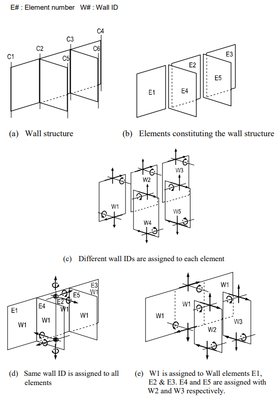
Walls in general structures are consisted of combinations of single (linear in plan) individual walls, thereby forming different geometric configurations. Each wall (group) is defined by entering individual unit wall elements. In order to reflect the true stiffness of combined walls individual wall elements are assigned with wall (combination) IDs.
Member forces of wall elements are produced for each story by wall IDs. If two or more wall elements at a given floor are numbered with a same wall ID, they are recognized as a single wall structure and each element force is combined together for the force output. However, wall elements assigned with an identical wall ID but located at different floors are recognized as distinct wall structures. Accordingly, it would be advisable to assign the same wall ID to all wall elements located in the same plan throughout all the floors in order to avoid confusion.
As illustrated in Figure 42 (b), 5 wall elements are required for modeling the wall structure shown in Figure 42 (a). Figure 42 (c) shows the output configuration when each element is assigned with different wall IDs to design them separately. The element forces are produced in the ECS of each element. Figure 42 (d) illustrates the output configuration for the case where 5 elements are designed as a single unit wall structure. In this case, all elements have the same wall ID. The forces for the assembled wall structure are produced at the centroid. The resulting forces are expressed in the ECS of the first element defined.
The stiffness of the combined wall, (a) is reflected in the structural analysis irrespective of wall ID numbering.
Element d.o.f. and the ECS
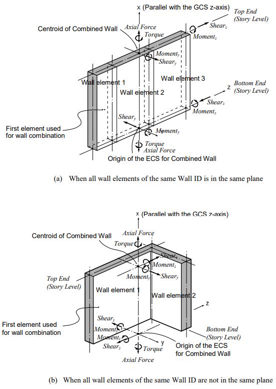
Wall element type 1 (membrane type) retains displacement d.o.f in the ECS x and z-directions and rotational d.o.f. about the ECS y-axis. Whereas, Wall element type 2 (plate type) has three translational and three rotational d.o.f. (refer to Figure 43). The ECS uses x, y, and z-axes in the Cartesian coordinate system, following the right-hand rule.
* Sheary and Momentz are additional components produced only for wall elements with out-of-plane bending stiffness.
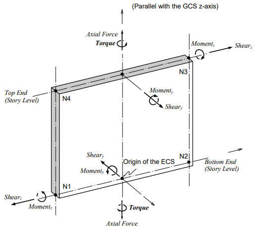
The ECS x-axis is set parallel with the GCS z-axis by default. The ECS z-axis is determined by the direction defined from the first node (N1) to the second node (N2), which are in turn used to define the range of target elements for a given Wall ID (refer to Figure 43). The perpendicular axis to the x-z plane becomes the ECS y-axis. When more than two wall elements are assigned with the same Wall ID number, the member forces are produced in the ECS of the first element (the element with the smallest element number). Refer to Figure 44. Connecting nodes must be entered from the bottom up. The nodes at the top and bottom of an element must be located in a plane parallel to the global X-Y plane. All the nodes must lie in a single plane. You should exercise caution when defining elements, as the ECS is defined according to the node numbering order.
Functions related to the elements
Create Elements
Material: Material properties
Thickness: Thickness of the element
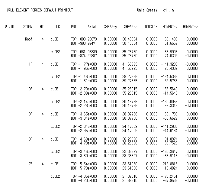
Output for element forces
The sign convention for element forces is shown in Figure 44. The arrows represent the positive (+) directions. Element forces are produced for each story by Wall IDs.