 Banner Title Products
OVERVIEW
Offsets
Offsets may be used on beam elements when the neutral axis is isolated from the nodes or if the neutral axes of connecting elements do not match. Offsets are defined based on the beam element nodes’ NCS. When the offset is set up in the axial direction of the element, it is interpreted as a change in element length.
When the shell element’s neutral plane is separated from the element nodes, or when the neutral planes of connecting elements do not match, offsets may be used. Offsets within a shell element may take on constant values in the direction of the element director.
Rigid End Offsets
A structure composed of frame members will be analyzed by taking the length of its members to be the distances between the intersections of element neutral axes. As a result, a rather large displacement—as well as end and center moment—may be calculated. To resolve this issue, beam and column connections or rigid end zones may be considered. If it is assumed that there is neither flexural nor shear deformation at the connections, the effective length for flexural and shear deflection may be expressed as the difference between the distance between the intersection of each members’ neutral axes (both endpoints) and the rigid end offset length.
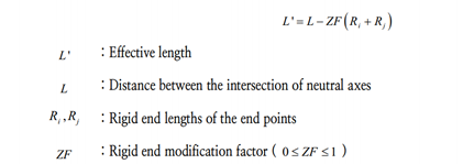
If the element length is only considered to be a function of the effective length, a small error may occur with the computation of the deformation occurring at the connection. The error may be controlled by using X Z Y eccentricity in the X-direction eccentricity in the Z-direction eccentricity in the Y-direction L ' : Effective length L: Distance between the intersection of neutral axes, Ri Rj: Rigid end lengths of the endpoints ZF: Rigid end modification factor ( 0 £ ZF £ 1 )ANALYSIS REFERENCE Chapter 3. Elements 47 | Section 6. Structural Elements the rigid end modification factor. This factor does not affect axial or torsional deformation, because, when calculating the axial and torsional deformations, the entire length of the element (L) is used. The rigid end offset may be used by incorporating the panel zone effects or by manually setting the rigid end lengths. In the latter instance, the rigid end modification factor is essentially 1.0. The user must be cautious of the following details when using rigid end offsets.
▶Calculation of element stiffness: When calculating element stiffness, the distance between the elements is used to calculate axial and torsional stiffness. When calculating shear or flexural stiffness, the effective length (after incorporating the rigid end modification factor) is used.
▶Calculation of distributed loading or self-weight: the distributed loading that is placed between the element nodes and rigid end offsets are only considered at the nodes as a shearing force, and the distributed loading on the remaining lengths are replaced as an equivalent shearing force and moment.
▶ When incorporating end releases: Rigid end offsets should be considered at the connections of column or girder members, in the case where either or both end connections have end releases due to a pinned connection.
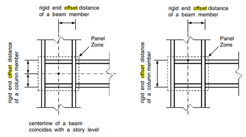
<Rigid end offsets built into a beam-column connection>
In structural engineering software, a member's offset shape should be applied for the following needs.
1. You can get accurate analysis results considering the member's offset.
2. Output of drawing reflecting member's offset shape.
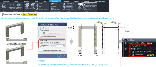
nGen provides the function to automatically generate the offset shape according to the joint rules between members.
The “Generate” function provides section offset, start/end offset, and cutback offset, and refer to the right for the shape of each reflected offset.
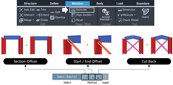
<Three Methods of Offsets in midas nGen>
Rule of Auto-generation
There are 6 different cases in midas nGen to perform offset automatically.
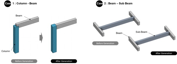
<Case 1-2 : Auto-generation of Beam & Sub-beam >
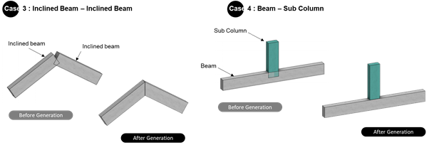
<Case 3-4 : Auto-generation of Beam & Sub-beam>
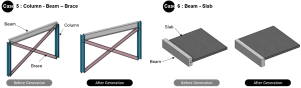
<Case 5-6 : Auto-generation of Beam & Sub-beam>
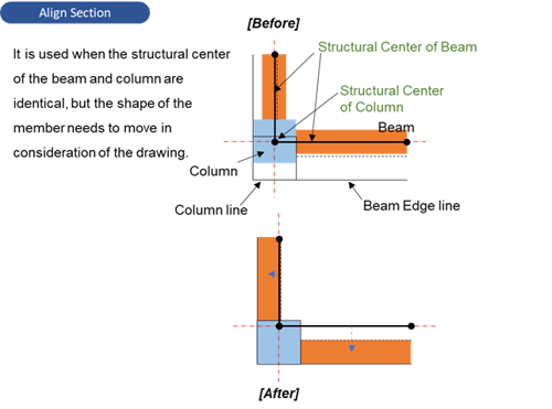
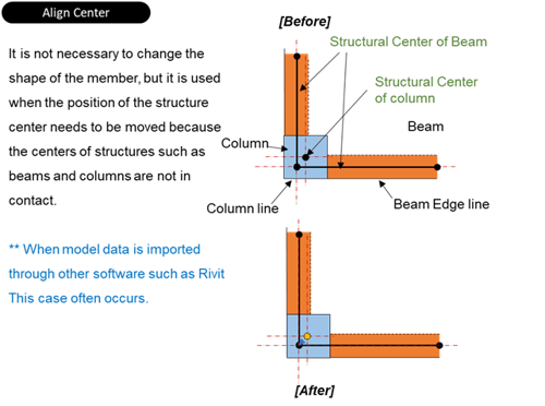
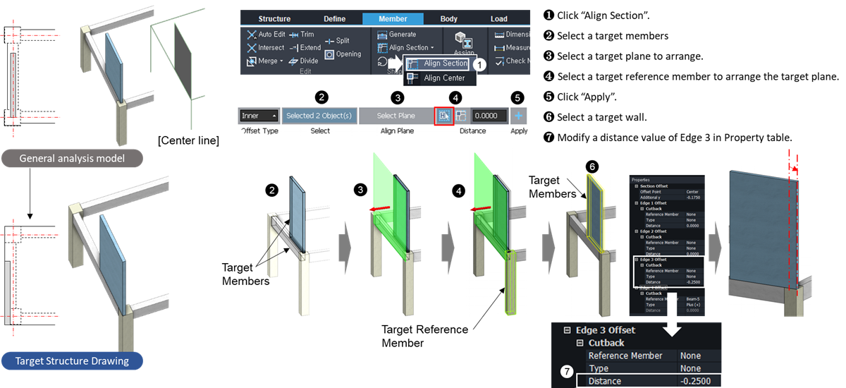
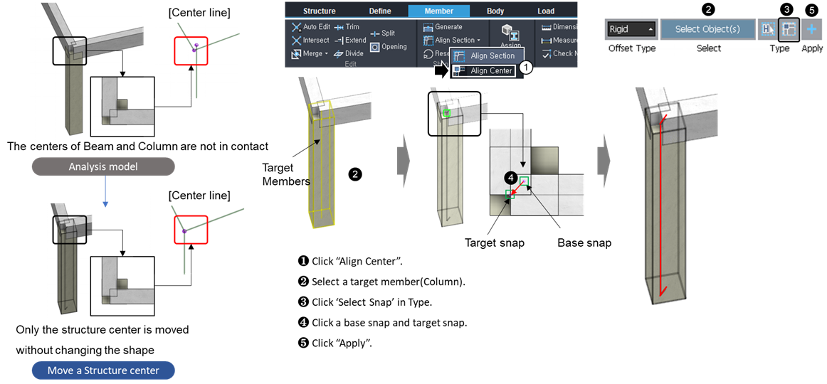
Align the section
Uses can also align the section and center of each member by the ‘Align Section’ function. In order to deliberately control the location, users need to know how to use it in midas nGen.
midas nGen provides a function to easily move the position of the member shape.
Align Section provides the following two functions.
-
Align Section: The center position of the member for actual analysis is not changed, only the position of the member shape is moved.
-
Align Center: The shape of the current member is not changed, only the position of the center of the member for analysis is moved.
This is a function to accurately reflect the shape position of the member when creating a drawing and supports the automatic definition of the analysis offset.
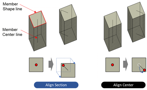
Align Section can be illustrated as follows:
Align Center can be illustrated as follows:
Tutorial for 'Align Section'
Tutorial for 'Align Center'
Analysis
For a full description of the basics or knowing the generation and alignment of offset, you can click to the following link
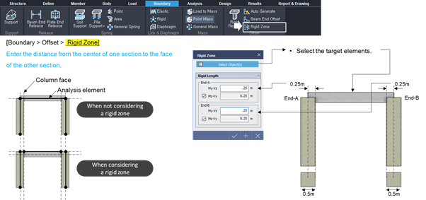
In general, 1D Element model is created by connecting the center of one section and the center of the other section. At this time, the member force, which is the analysis result, is generated from the endpoint as shown in the right figure 'No Beam End Offset'.
However, as for the actual member force, the cross-sectional position of the beam in contact with the column and the position at which the member force starts (the side face of the column) must be considered.
nGen enables accurate design by obtaining analysis member force by providing beam end offset and rigid zone functions. For models with beam end offset and rigid zone, a model with a rigid link installed by an offset distance as shown in the right figure 'Apply Beam End Offset' is automatically generated and reflected in the analysis.
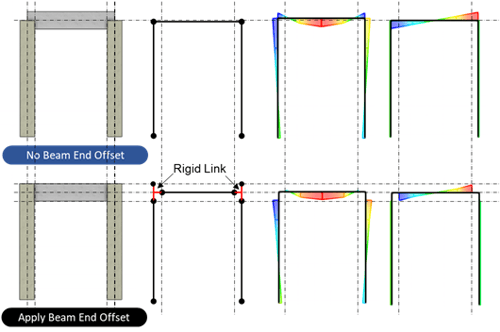
<The difference with and without offset in analysis>
I am going to introduce the basic method of analysis considering offset in midas nGen. The following functions are defined easily.
- Beam End Offset Function
- Rigid Zone Function
- Auto Generate Function
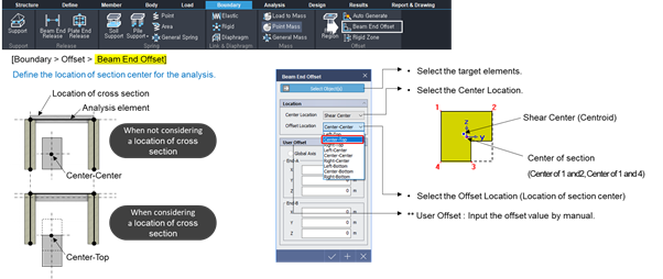
<Beam End Offset function in midas nGen>
<Rigid Zone function in midas nGen>
<Auto Generate function in midas nGen>