 Banner Title Products
OVERVIEW
In the previous version, users can check the mesh quality only after performing analysis. Thus, every time users want to check the mesh quality, the analysis should be performed again, which is inconvenient and time-consuming.
The newly introduced Mesh Mode provides the ability to check and modify the mesh size and shape. Besides, mesh creation errors in the preprocessing stage can be detected without analysis.
If users run Mesh View Mode, you can check the mesh shape immediately.
Mesh Setting
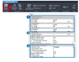
First of all, a settings dialog in mesh view mode allows users to control the overall mesh size. Here, users can set the mesh size separately for each part and determine the mesh shape.
Triangular and square shapes categorize the mesh shape. Each model can be composed of only triangular elements or a mixture of quadrilateral and triangular elements.
 • Control of the mesh size
• Control of the mesh shape for 2D and 3D element
1. Default Division: Define the mesh size which is created automatically when the analysis is performed.
[Method]
1) Length: Define the mesh size manually.
2) Division: Define the mesh size by specifying the number of divisions.
3) By Design Setting: Define the mesh according to the 'Member Check Points' setting at Design Setting. (1D only)
4) Smart Size: Define the mesh size automatically in accordance with the shape of the model.
2. Tolerance
• Merge Tolerance: Define Merge Tolerance to combine two or more neighboring points as a single point.
3. Surface Mesh Control: Define 2D mesh generation method.
1) Element Type: Generate a mesh with the selected shape.
*Note: Quadrilateral meshes provide a more stable analysis, but for complex geometric shapes where quadrilateral meshes are difficult to generate, it is better to generate a triangular mesh.
2) Element Size Growth Rate: Define the internal mesh density to create a mesh with higher quality.
3) Try Mapped Mesh: Select whether to generate Mapped Mesh or not.
*Note: The Mapped Mesh maps the selected shape with square domains and generates a mesh on the mapped domain.
Mesh Size Control
Next is the mesh size control function.
This is a function for controlling the local mesh size.
The first icon is used for the mesh size of the edge in 1D member or 2D member, and the next icon can control the mesh size of a 2D face by member unit.
Information of mesh size is saved in the tree as shown on the right and can be edited.
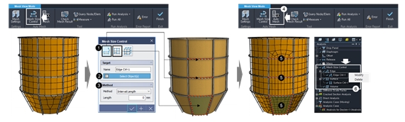
1. Select Element Type. (1D element or edge of 2D element, 2D, and 3D element)
2. Select the target elements.
3. Select the mesh method and value to divide.
4. Run "Auto mesh". (When the information for a mesh control is modified by "Mesh Setting" or "Mesh Size Control". Mesh shape can be displayed with "Auto Mesh" feature.)
5. Check the meshed shape.
6. To modify, click tree > Analysis Tap > Mesh Size Control> Mesh Name.
Check Mesh Result
This is a function that finds errors that occurred in the created mesh before performing the analysis. The first option finds cases where the mesh is created without considering the interference between two members.
The first figure shows that the two members' meshes did not interfere with each other, and the information of the two members is provided in the check result table. The figure on the right is a case with a regular mesh shape created with considering interference.
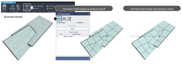
• If the mesh shape of the two elements does not interfere with each other information of members is displayed.
• If the mesh is created normally, the mesh shape of two elements is generated to interfere with each other.
The third option finds the abnormally longish elements.
If the element has a longish shape, we can't get the exact results in FEM. To find the longish shape, we should enter the Max threshold value. The element's threshold value is the ratio of the square of the perimeter to the area multiplied by four pi.
For example, in rectangular elements, when the aspect ratio is 1:1, then the threshold value is 1.27, and when the aspect ratio is 100:1, the threshold value is 32.47. In triangular elements, when the aspect is 1:25, then the threshold value is calculated as 16.57.
[How to get the maximum threshold value]
Threshold Value = (Perimeter2)/(4π*Area)
Example:
- 1:1 rectangle = 1.27
- 100:1 rectangle = 32.47
- 1000:1 rectangle = 318.95
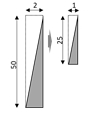 Threshold Value
= [25+1+√(252+12)]2/(4π(25*1/2)) = 16.57
The "Check Mesh Result" box shows element-21 since the ratio is larger than the set maximum threshold value of 20.