 Banner Title Products
OVERVIEW
The footing is a structural member that safely transmits the load of the upper building to the ground, and is the first construction member of the building. The basic method of footing design is to distribute the load so that the size per area of the load transmitted from the upper part of the building is less than the strength that the ground can support, that is, the bearing capacity. With this function, the footing is a structure installed between the ground and the column or wall immediately above it, and the important point in the basic design is to reduce the total amount of settlement and prevent the occurrence of immobile settlement.
In a general building, the footing design is to determine the area of the footing, the thickness of the footing and the amount of required rebar.
In this topic, we deal with starting from finding out the Footing Type necessary for a building and proceeding with the Footing Design step by step in nGen.
1. Footing Type
1-1. Supporting Scope for Footing
midas nGen supports modeling, analysis and design of various footing systems.
- Enables to design of members connected to the footing.
- Provides tools to quickly model files.
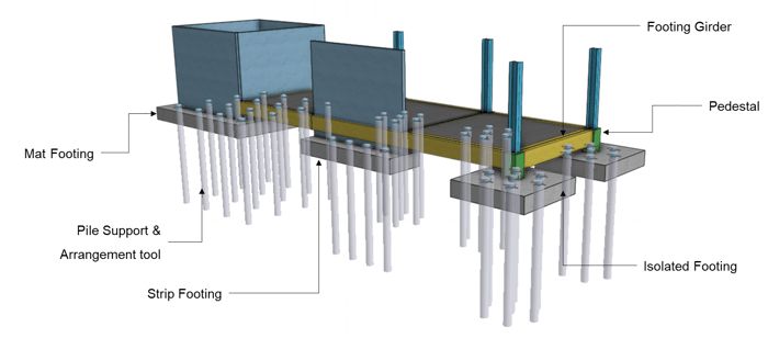 <Supporting Scope for Footing>
1-2. Footing Type
Footing can be categorized by Member and Design type. There are three types of footing members.
- Mat Footing, Strip Footing, Isolated Footing
There are two types of footing design.
- Rigid Design: Footing is assumed to be infinitely rigid. The bearing pressure against the bottom of the footing follows a planar distribution where the centroid of the bearing pressure coincides with the line of action of the resultant force of all loads acting on the footing.
- FEA Design: Footing is designed according to the results of finite element analysis. Since it is designed based on analysis, more accurate analysis results can be obtained.
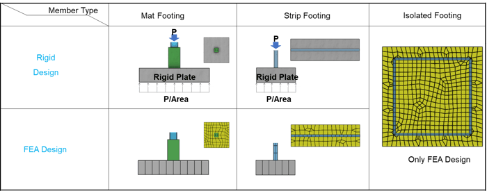 <Supporting Scope for Footing>
1-3. Support for Footing
Soil Spring and Pile Spring is supported in midas nGen.
- Supported Soil Spring Property: Linear Elastic, Compression-Only
- Supported Pile Spring Property: Linear Elastic, Tension Only, Compression-Only, General
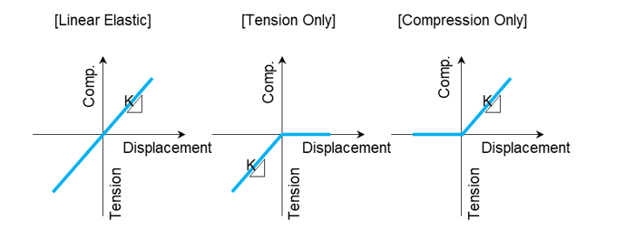 <Support For Footing>
2. Footing Design
2-1. How to Design Isolated Footing with Rigid method
An isolated mat footing transfers the loads from a single column to the supporting soil. The size of the footing is determined by the allowable soil bearing pressure. The footing is designed for flexure, punching or two-way shear and one-way shear. The depth of the footing is generally governed by punching shear.
The calculation of soil pressure in serviceability state and the ultimate state as below.
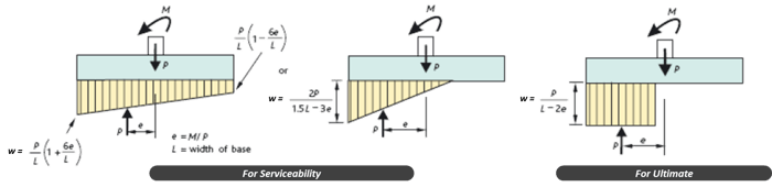 <Calculation of Pressure Distributions by Each Status>
2-2. How to calculate a design bending moment
The value of the design bending moment at the column face is applied to the calculation.
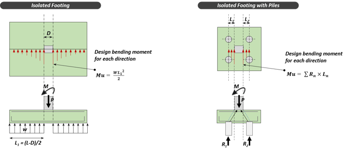 <Calculation of Bending Moment>
2-3. How to calculate a design shear force
The soil pressure inside the shear face or shear perimeter is not considered in the design shear force calculation, assuming the load is transferred to the column.
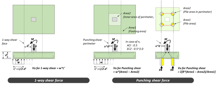
<Calculation of Shear Force>
2-4. Supporting Design Items for Rigid Method
| Ultimate Status |
Flexural design |
All |
|
1-way shear design |
All | |
|
Punching shear design |
All | |
|
Serviceability Status |
Stress limitation check |
Only Eurocode-2 |
|
Crack width check |
Only Eurocode-2 | |
|
Linear creep check |
Only Eurocode-2 | |
| Stability |
Sliding |
All |
|
Bearing capacity of Soil |
All | |
|
Bearing capacity of Pile |
All | |
|
Overturning |
All | |
| Sliding | All |
For a full description of the basics or to know the type and design of footing, you can click on the following link > Footing - Type & Design
In this topic, we will cover how to build the foundation of the building.
1. Create Footing
1-1. Isolated Footing
Isolated footings (also known as Pad or Spread footings) are commonly used for shallow foundations in order to carry and spread concentrated loads, caused for example by columns or pillars. Isolated footings can consist either of reinforced or non-reinforced material.
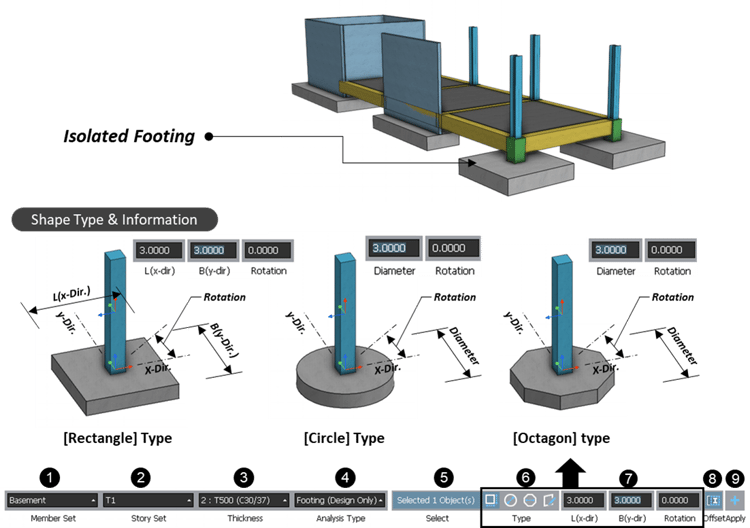 <Create Isolated Footing>
1-2. Strip Footing
Strip foundations (or strip footings) are a type of shallow foundation that is used to provide a continuous, level (or sometimes stepped) strip of support to a linear structure such as a wall or closely-spaced rows of columns built centrally above them.
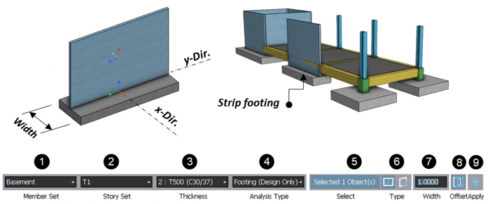
1) Select a member Set
2) Select Story set.
3) Select Thickness of footing.
4) Select Analysis type. (Refer to “Footing Type” guide.)
5) Select target columns or pedestals.
6) If you select “By Drawing”, you can create a footing by manual.
7) Enter a width value.
8) Click to turn on/off an offset option. (Footing is placed considering an offset Info. of the wall.)
9) Click “Apply”
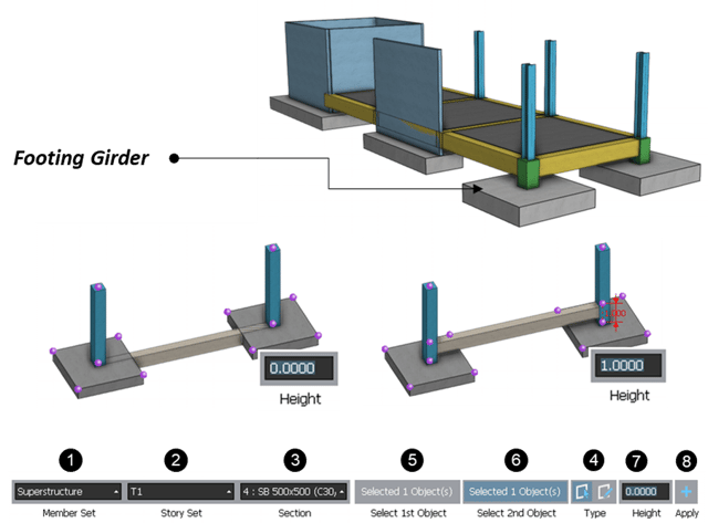 <Create Footing Girder>
- “By Select”: by selecting two vertical elements.
- “By Drawing”: by clicking two points.
1-4. Pedestal
A concrete pedestal is a compression element provided to carry the loads from supported elements like columns, statues, etc. to footing below the ground. It is generally provided below the metal columns. In general, the pedestal width is greater than its height.
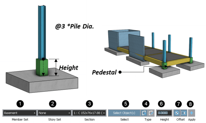
<Create Footing Girder>
- “By Select”: by selecting two vertical elements.
- “By Drawing”: by clicking two points.