 Banner Title Products
The Objective of This Guide
The analysis and design of the crane moving load calculate the influence of the vertical and horizontal loads (Max./Min. node displacement, Max./Min. member strength, and reaction) caused by moving the crane on the crane girder, and it means a series of analyses and design processes for designing crane girder under common structures.
This material explains the use of the crane girder analysis and design features in midas nGen, and provides the relevant technology and verification data for this analysis and design.
Two types of crane girders can be supported by nGen. As shown in Fig. 1, there is a "General (type) Crane Girder" that resists vertical and horizontal forces caused by the crane itself. There is a "Composite (Type) Crane Girder" which can be combined with horizontal truss and back girder to integrate with horizontal force.
 Figure 1. Concept of General Crane Girder
Generally, when the crane capacity is not large, a General Crane Girder can be used. In the case of a crane having a large capacity and a large horizontal force, as shown in Fig. 2, Composite Crane Girder Resistant with the back girder and back truss can be used.
Chapter 1 and 2 provide the concept of general crane girder and tutorial data. And Chapters 3 and 4 provide the concept of composite crane girder and tutorial data.
Introduction of General Crane Girder (Moving Load Analysis and Design Technical Background)
1.1. Element Concepts (Introduction of 1D-Beam Elements and Supportable Section)
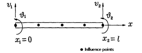
General Crane Girder is best simulated with a 1D Beam to analyze the impact of crane travel on the elements. Influence points are used to analyze the impact of moving weights (Figure 3). Here, the more Influence Points, the more accurate the moving-weight analysis results are, and the number of influence Points can be pre-specified by the user.
Meanwhile, General Crane Girder in the analysis and design supports 1D Beam member with certain sections, or, as shown in the Table-1, H-shape, H-shape with Flange Plate, H-C Combined Shape are used mainly.
| Type | Combine Type | Single-Sided Shape | Design Substitution |
| H-Shape | - |
|
H |
| H-Shape with Flange Plate | - | 
|
H-Shape with Flange Plate |
| H-C Combined Shape | Downward | 
|
H |
Table 1. Crane Girder Main Section Shape
1.2. Influence Points of Concept
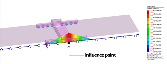
Figure 4 shows the calculation of the influence line results that were calculated by the unit weights over each point. Each of the influence points you specify has the following impact line results, where you can enter the wheel information of the crane to determine the analysis (maximum) member force, etc. for each Influence point.
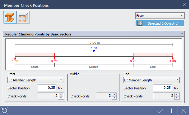
1.3. Check Position Concept
Check Position is an in-member calculation point that is recognized when performing a design after analysis, and the program assigns four sections (Figure 5) as Check Position, and you can adjust the number of Check Positions according to your intentions. The selected member is determined by NG, OK or Not Checked, which of the check positions the member has the most unfavorable Rating, and provides a one-of-a-kind view of the calculation report in the output of the detailed calculation.
General Crane Girder: Introduction to Analysis and Design Procedures
This chapter uses the Crane Framing Plan in 3 spans (column 14 to column 17) of Figure 6 to follow a simple General Crane Girder model: Each column has a column spacing of 10m, and cranes with a capacity of 100Ton are located between columns D and E. Each crane girder is simply supported so that no source moment occurs.
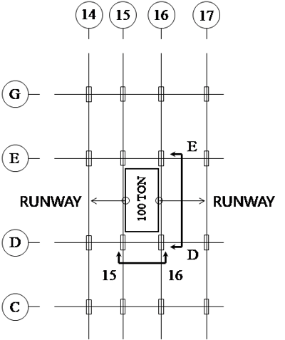
Figure 7 shows crane wheel information and crane girder information. Crane bridge has a span of 10m, hook approach has 1m. The crane has a capacity of 1,000 KN, trolley and Hoist weighs 250 KN, and has a self-weight of 250 kN. There are eight wheels at each side of the crane bridge, the wheel load acting on each wheel is assumed to be the same.
Download the full pdf file from the form below.